
Custom Front Tool-Head Carrier Plate for Qidi Plus 4
Obliczymy ostateczną cenę na podstawie wybranego pliku. Sprawdzisz ją i zaakceptujesz przed płatnością.
Zapisane na tym urządzeniu.

A Custom Front Tool-Head Carrier Plate for Qidi Plus 4, also with mount for a Beacon/Cartographer module
- Ocena
- 5 / 5
- Polubienia
- 112
- Pobrania
- 487
- Wydruki
- 5
- Wyświetlenia
- 3929
- Oceny
- 3
Aktualizacja u źródła:
Informacje o modelu
- Źródło
- Printables
- Kategoria
- Other Printer Parts & Upgrades
- Licencja
- Creative Commons — Attribution — Noncommercial — Share Alike
Qidi Plus 4 Custom Front Tool-head carrier plate
A Custom Front Tool-Head Carrier Plate for the Qidi Plus 4 3D Printer which serves as a base framework to attach various mods to. A handful of some basic attachment mods are also provided, such as a Beacon/Cartograper Eddy Current mount, a stock inductive probe mounting adapter, and modified hotend heatsink fan duct. I also have a front-mounted 5015 fan-blower part-cooling mod that builds on top of this carrier-plate framework.
Update History
23-March-2025: As a heads up, I'm slowly converting some of the models here from using inserted metric hex-nuts, to using inserted metric square nuts instead. I've been searching for a reliable and easy to install approach for providing a means for metric bolts to attach to the parts, and as of right now it's looking like square metric nuts will be the way forwards to achieve that. Check back occasionally as I continue to convert any hex-nut based models to square-nut instead. Metric square nuts are readily available for low cost online.
25-March-2025: I've now uploaded an M3 square nut insertion version of the tool-head carrier plate. At this point in time I have no plans to convert the other attachments here to use square nuts instead as they appear to be working just fine as is. It should also be noted that with the square nut variant that 20mm long M3 bolts must be used to bolt the hotend to the carrier plate, as opposed to the stock 16mm bolts, due to the square nuts being recessed a little further.
27-March-2025: I will state that my official recommendation is to print and use the square nut insert version of the models over the heat-set variants, however I will leave the heat-set models up as I'm aware that some prefer the appearance of these models.
17-April-2025: Pushed a stiffer variant of the tool-head plate for people to try
20-April-2025: Updated the stiffer variant to be even more stiff. This should eliminate any potential flexing when using mods that exert a high degree of torque against the plate (such as the 5015 Front Blower fan mod)
22-April-2025: Update the stiffer version Plus4-Font-Carrier-Square-Nut-Stiff with an adjustment to the angle of the plane to the hot-end mount point. This adds a small amount of tension to the hot-end against the plate which actually keeps it both more sturdy and straighter. This version of the plate is the one that you ideally want above all others.
24-April-2025: Update of stiff model with a tweak to better handle the self-tapping screws that holds the front PCB daughter-board to the plate
17-June-2025: I've uploaded a revision to the carrier plate model that makes it easier for FFF printers to print the overhanging sections. This part still retains all the important functional features, but simplifies some sections, and adjusts the angle and shape of over-hanging areas to give a cleaner appearance.
8-July-2025: It was found that the FFF simplified model posted on 17-June-2025 was a little too long to remain compatible with the stock part cooling fan's clearance requirements. I've uploaded a new model called: Plus4-Front-Carrier-FFF-Stiff-Square-Stock-Cooling which is the same model, but a little shorter at the bottom and should retain compatibility with the stock part cooling fan. The down-sides to this model is that there is less material for the square nuts to hold their position, so be careful when torquing the bolts that hold the front and back plates together. My apologies for any inconvenience.
Introduction
The Qidi Plus4 is a great printer, but its tool-head design isn't friendly towards modding, with its injection molding, and somewhat fragile design. There are limited mounting points, and most of those are self-tapping screws into plastic, which is less than ideal.
This plate attempts to solve that issue by presenting a model that can be fairly easily printed on a Plus4, and can be used to replace the front-carrier plate that holds the extruder unit, hotend, hotend fan, and inductive probe mount.
The aim of this model is to make all mounting holes be secured with either heatset inserts, or square nut inserts, for greater robustness, without sacrificing too much in the way of weight or stiffness. All mounting point holes are symmetrical about the vertical center line.
This new plate model is incompatible with the stock cover, but the goal here is to provide a better mounting framework for people to make their own cover designs that are easier to print than the fairly complicated stock cover.
This plate is also slightly wider than the stock plate, with its width being equal to the stock front plate with the cover attached. In doing so, this preserves the X end-stop location behavior, and no firmware adjustments need to be made to account for the use of this plate. This plate is also compatible with the stock part cooling fan and does not interfere with the clearances required for that fan.
Additionally locations for heat set, or square nut, inserts are added to provide the ability to bolt the stock back plate to the replacement front-plate using M3 bolts. This removes the stock self-tapping screws into plastic which are unreliable over time. This provides a MUCH sturdier way to clamp the front and back plates together, which in turn leads to better input shaping performance.
The stock Qidi tool-head carrier plate weighs in at 35g. This new plate, when printed using the profile recommended below in a PPA-GF filament, will come in at approximately 43g. The added weight of the 3D printed tool-head is offset by the removal of the stock front cover.
Using square nuts results in a final model that weighs just 48g with all the nuts inserted. It is my express opinion that the square nut insert version is superior to the heat set insert version.
How to print
Filament Recommendations
Due to the elevated chamber temperatures that the Qidi Plus4 is capable of, and due to the proximity to the print bed, this part has some very particular property requirements:
- This part is best printed using a filament that has a Tg (Glass Transition Temperature) AND HDT (Heat Deflection Temperature) of >100C
- When I said both should be above 100C, I meant it
- PC-CF will generally be the best affordable option here.
- PPA (PAHT), with either CF or GF filling for added stiffness is also a decent choice, however some blends have a Tg of 80C, which may cause warping issues.
- Some high temperature tolerant blends of PET with a high Tg may also be suitable
- Be sure to check filament TDS
I personally used Qidi's newly released PAHT-GF filamentThat filament is a little expensive though. There is some conflicting data with regards to its Tg though.
I have successfully used 3DXTech PC-CF for this part. This is an expensive filament, but it is, IMO, one of the provable best options on the market, and it is this filament that is now set as the cover photo for this project.
When printing with either PC or PPA, it is essential to thoroughly dry the filament for best results. If you print and see excessive stringing or oozing, then this is usually a good indication that your filament is not dry.
Slicer Setup
The following all assumes you have already calibrated your filament correctly for temperature, flow rate, pressure advance, and retraction settings.
Firstly, I highly recommend using the following print profile for Orca Slicer.
Orca Print Profile for Tool-head Project
This profile, while slower, will give excellent resolution and a good looking finish. It's worth it to take the little extra time to print this part well, especially since it forms the foundation that all your future prints will rely upon. This profile also generates some internally hollow sections within the final print part, but this is an intentional trade-off between weight and strength. When flexed side-by-side, the printed part feels at least twice as stiff as the stock Qidi part.
If you are using a different slicer, or you are unwilling to use the above recommended profile, then use the following:
- 0.2mm initial layer height
- 0.1mm layer height all other layers
- Use a 0.4mm nozzle. A 0.6mm nozzle may work but there are a handful of very fine clearances where a 0.6mm nozzle will struggle with.
- Use 5 walls.
- 20 bottom layers and 2.1mm bottom shell thickness
- 21 top layers and 2.1mm top shell thickness
- An Ensure Vertical Layer Thickness setting of “All”
- A 40% honeycomb sparse infill density
Secondly, and due to the need to keep the bearing carriers as dimensionally accurate as possible, the part is designed to be printed in this orientation, which unfortunately requires the need for some supports. This results in a couple of the faces having their appearance affected by the use of supports, but when everything is installed these faces are hidden by other components that are attached to the carrier plate, and so this is deemed as an acceptable trade-off. 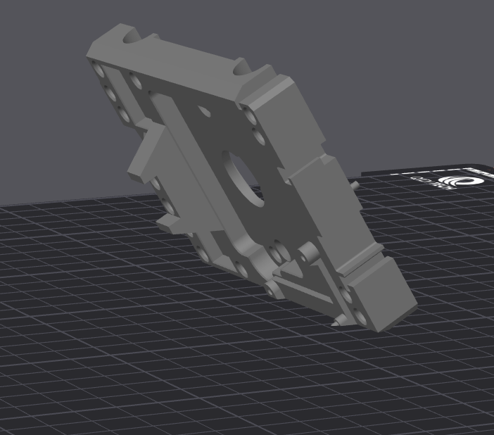
Use the “Lay On Face” tool and place the part on the diagonal edge surface. When supports are applied, the part should remain stable throughout the print, given any decent build plate adhesion. Please ensure that the model is placed upon the right-side slant, as a number of the overhanging regions have been tuned for this orientation.
Just to be clear, the part is placed upon the pale-blue face as shown in the below image:

A brief video demonstration of how to orient the plate on the print-bed within the slicer:
Thirdly, apply support blockers to the various mounting holes like so: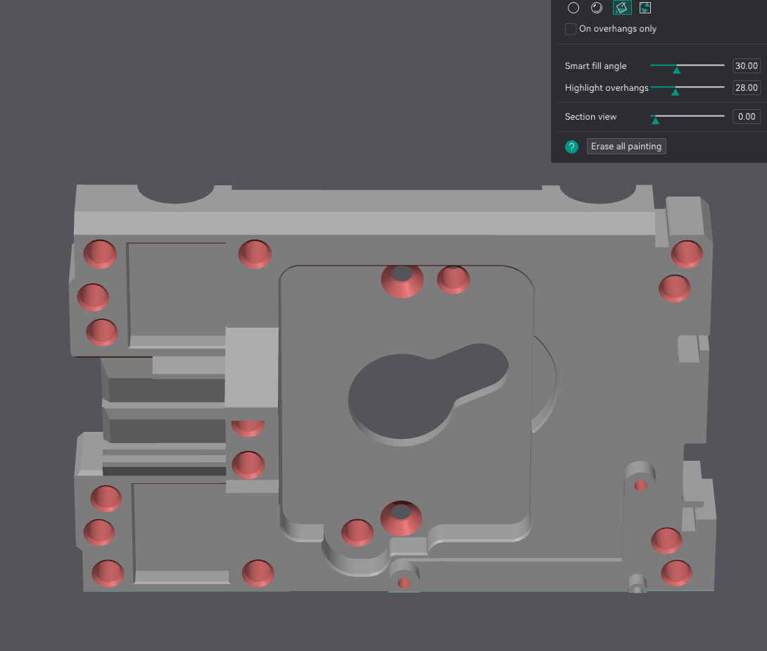
This will minimise the slicer's tendency to allocate excessive amounts of support where it's not really needed. This will also make support removal much easier post-printing.
Be sure to also print the slide-on cable clamp which secures the cables that pass from the rear tool-head PCB to the front.
Post-processing
Clean up the print via your usual methods, although it should already be fairly clean. I find it best to use the metal scraper that came with the Plus 4 to quickly scrape away any support residue, and this should result in a very clean final appearance.
Heatset Insert Variant
Install M3x6mm heat-set inserts in each of the 16 locations on the front of the tool-head carrier plate. For the 4 heatsets that are used to clamp the front and back plates together, I recommend using a long M3 bolt screws right through to clear out any melted filament that resulted from inserting the heatsets, which will make it easier to fit the clamping bolts that need to pass through the back of the plate.
Square Nut Variant
All M3 nut insertion channels are 2.5mm tall, and 5.6mm wide. It is recommended to use M3 square nuts no thicker than 2.35mm, and no wider than 5.45mm
Push M3 square nuts into the slots provided to give M3 bolts a metal-based thread to secure onto. This should be a fairly quick and easy process. The slots are designed to be a little tight to minimise the chance of the nuts falling out prior to mounting bolts being screwed into them.
When inserting nuts, be sure to remember that there are two nuts inserted from the rear that are used to hold the extruder in place. The following photo outlines where all the nuts must be installed. In total, the part takes 16 x M3 square nuts

Installation
Note: Please use Blue Loctite, or a similar, thread locking agent to ensure that threads do not come loose over time. If the extruder motor, extruder itself, or the hotend manages to work their way loose, this can cause damage to the electronics or the printer in general.
Remove the hotend, extruder, heatsink fan, and PCB's from your existing front tool-head carrier plate. Also unscrew the extruder stepper mounting screws. Remove any rear tool-head carrier covering. Unscrew the 4 screws that clamp the front and rear plates together.
There is a pictorial installation/assembly guide hosted here. That guide is part of my front-mounted blower project, but the installation of the tool-head is the same for the two projects.
Installation is then the reverse of the above procedure. The only real tricky part is the stepper motor. It helps to hold the extruder stepper by the gear shaft to allow the stepper mounting screws to bite into the stepper's molunting screw holes. Everything else should be straight-forwards after that.
Eddy Current Sensor - Beacon/Cartographer Mount installation
Print out the Beacon/Carto mount model. I recommend again using the same print-profile as for the main custom plate, but this time set the infill pattern to a 20% Honeycomb infill density.
Once printing of the model is completed, insert 2 of M3x6mm heatset inserts (or M3 square nuts if that model was printed) into the bottom for clamping the eddy sensor to the mount, and 2 of M3x4mm (or 3mm) heatset inserts into the heatsink fan mount for bolting the fan to the sensor mount.
Install the Eddy Current Sensor, fan, and finally the mount onto the custom carrier plate, as shown in the opening photo for this model.
Stock Inductive Probe Installation
If you will be re-using the stock inductive probe, then print out the adaptor piece. Press an M3x4mm and an M3x6mm heatset insert into the adaptor.
Mount the adaptor to the custom carrier plate as shown below using 3 of M3x6mm SHCS bolts.

Now attach the stock inductive sensor probe to the adaptor, as show below, and affix using M3 SHCS bolts.

When using the inductive probe adaptor, the [smart_effector] config section within printer.cfg will need to have it's y_offset adjusted to -7, instead of 1.3
[smart_effector]
pin:U_1:PC1
recovery_time:0
x_offset: 25
y_offset: -7           # Adjust y_offset to -7 to account for adaptor plate
Support
Enjoying my work? Buy me a coffee! https://ko-fi.com/stew675