
Radar Presence Sensor with IR Proxy ( LD2410 (C)) and Tilt Mount
Obliczymy ostateczną cenę na podstawie wybranego pliku. Sprawdzisz ją i zaakceptujesz przed płatnością.
Zapisane na tym urządzeniu.

This is an easy to build Motion Sensor and IR Proxy that integrates with Home Assistant. Tiltable, mountable on Skadis.
- Ocena
- 0 / 5
- Polubienia
- 44
- Pobrania
- 203
- Wydruki
- 0
- Wyświetlenia
- 2184
- Oceny
- 0
Aktualizacja u źródła:
Informacje o modelu
- Źródło
- Printables
- Kategoria
- Electronics
- Licencja
- Creative Commons — Attribution — Noncommercial
This Radar Presence Sensor is easy to build and pretty cheap considering its performance. The firmware uses ESPHome. The sensor uses the universal ball-joint design so it can be oriented for accurate detection. I provide a skadis mount which uses T-Nuts, but you can remix the base from the original design to fit your needs.
Both V1 and V2 support configuing the ESPHome Bluetooth Proxy.
V2 Notes (IR control)
We can use the remaining GPIO pins to add Remote Control functionality to the Presence Sensor. The image below shows how the components are mounted. We bend the legs of TSOP IR receiver and IR LED.
I will post another iteration of the top cover which omits the IR Receiver shortly.
Components required:
IR LED (6mm)
IR receiver (Use a piece of tape (such as kapton) to isolate the metal body of the recevier from existing components on the PCB)
N-channel Mosfet (2N7000) (Can be skipped but the range would reduce)
47ohm resistor for current limiting
2Kohm resistor to pull down the Mosfet gate
LD2410 (C) Presence Sensor (same as V1)
Existing devices can be easily upgraded. The full schematic, as well as the component placement is shown below.
The overall size of the sensor remains the same, however the case needs to be reprinted to allow space for the components. The IR receiver is intentially located to prevent it from receiving its own emitted signal.


The IR LED protudes from the case to obtain higher coverage.
The IR receiver uses very little power, so to keep soldering simpler we use two GPIO pins as voltage source. In esphome it's achieved as follows:
switch:
- platform: gpio
pin: GPIO19
id: ir_in_power
internal: true
restore_mode: ALWAYS_ON -> Acts as a 3.3v source
- platform: gpio
pin: GPIO23
id: ir_in_pgnd
internal: true
restore_mode: ALWAYS_OFF -> Acts as GND
remote_transmitter:
- id: ir_tx_front
pin: GPIO26
carrier_duty_percent: 50%
remote_receiver:
- id: ir_rx_front
pin: GPIO5
dump:
- pronto
Full esphome config is available on my Github repo
V1 Notes (still applicable)
Most LD2410 (C) modules sold have a convenient pinout that matches the right row of D1 Mini. This means you can simply solder the module directly to the board as a sandwich. No wiring needed. I would recommend putting some double sided tape to keep it stable, and this helps with soldering.
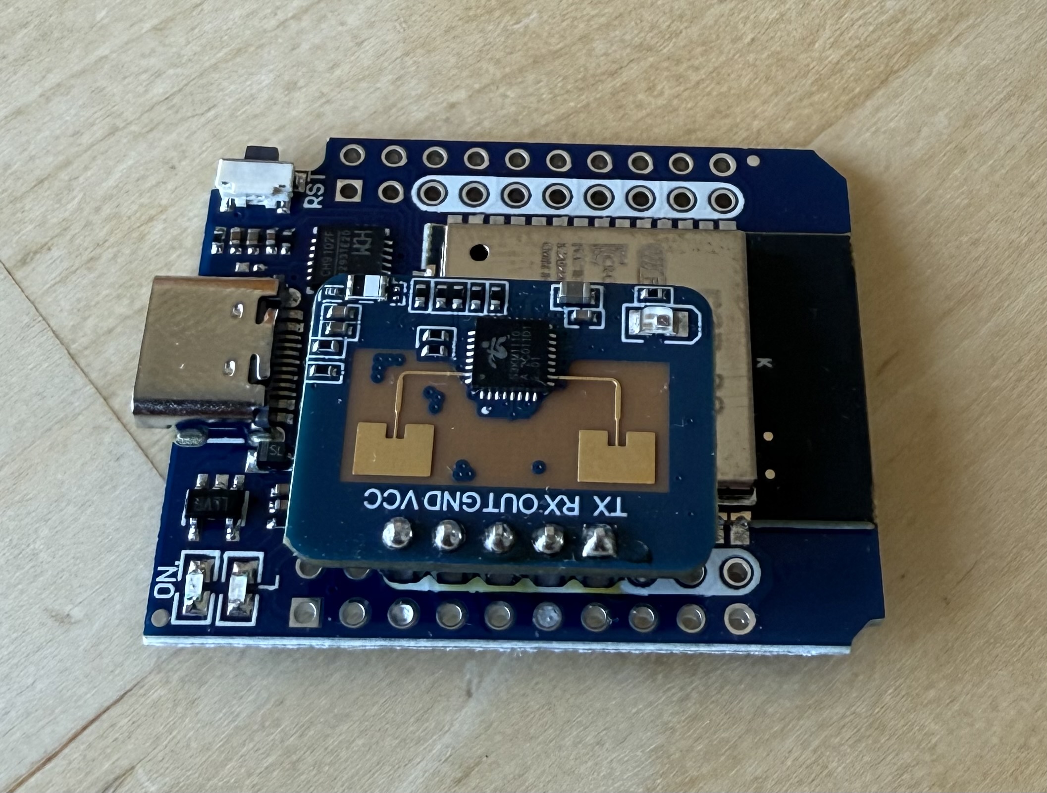
Pinout:
LD2410— D1 Mini
VCC — VCC
GND — GND
OUT — IO16
RX  — IO17
TX — IO21Firmware: Follow ESPHome guide linked above for a starter firmware. A slightly modified version is available on my GitHub.
For the aesthetics I wanted to go with here, unfortunately the screw slots on the front cover need supports. Any kind of support is fine and should be very easy to remove. Otherwise, there are alignment indents in the base of the case that have supports baked in. Similarly some holes are also supported.
The ESP is pressure fit to the bottom case as shown below.
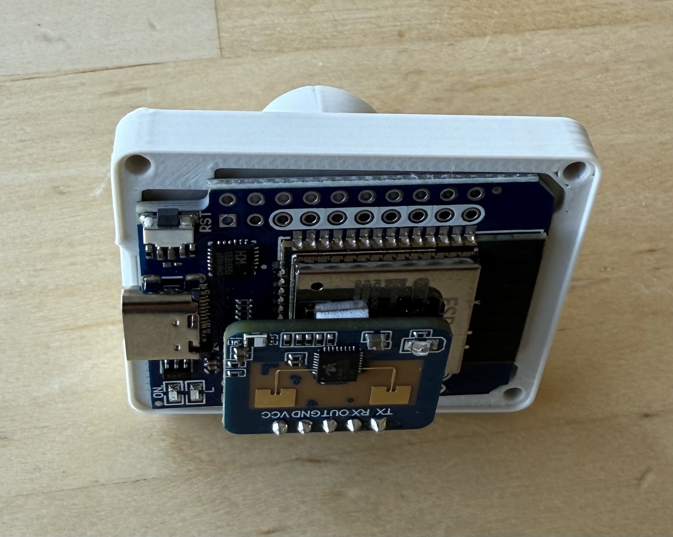
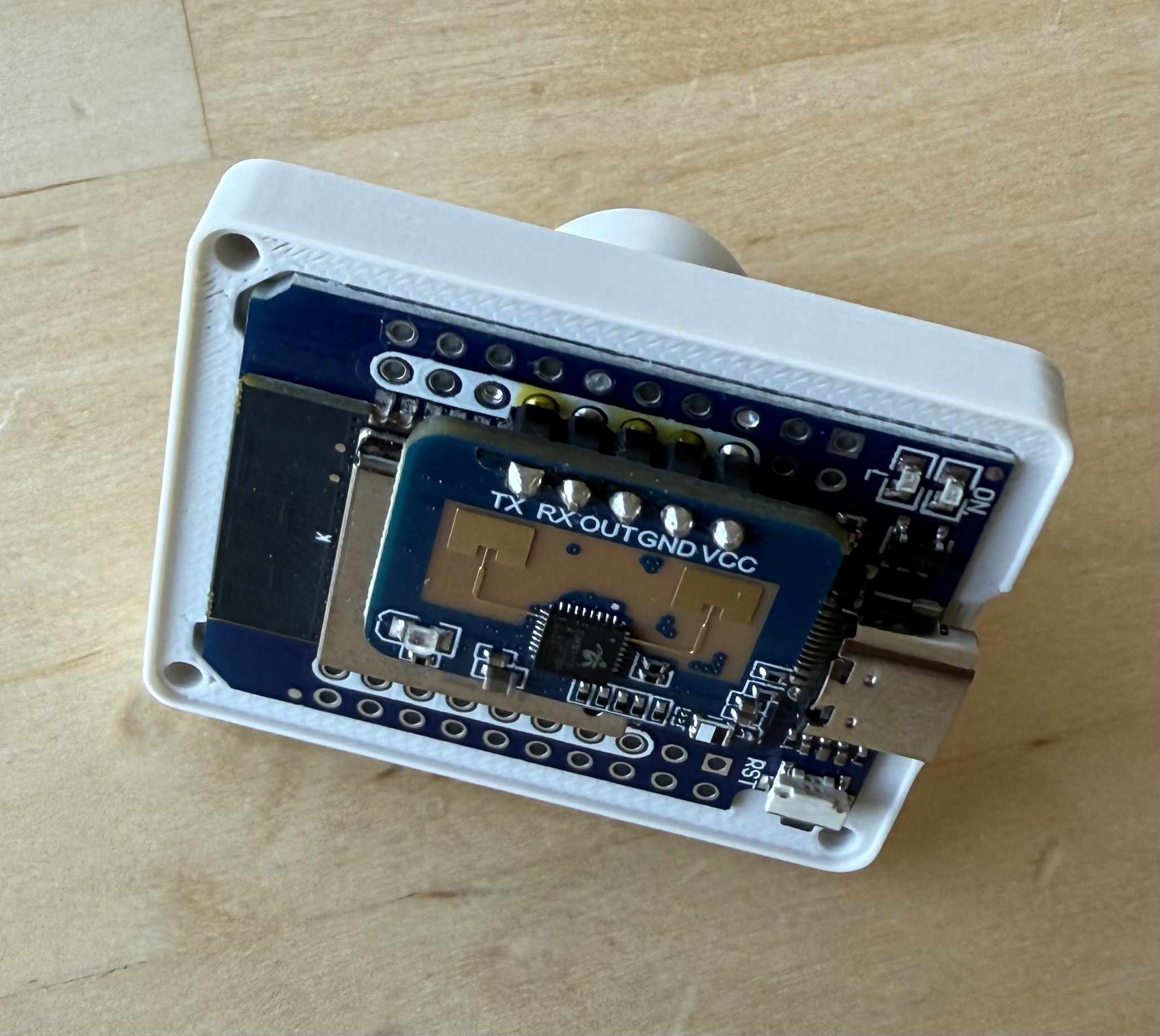
Apart from this, we need 5 16mm 2.5mm diameter screws (which go into undersized holes). I used BT2.5 self threaded screws. I know M2.5 screws work well too.
Use M2.5 screw and nut for the T-Nut. Stick the Alignment guide to the base of the ball-joint I provide as shown.
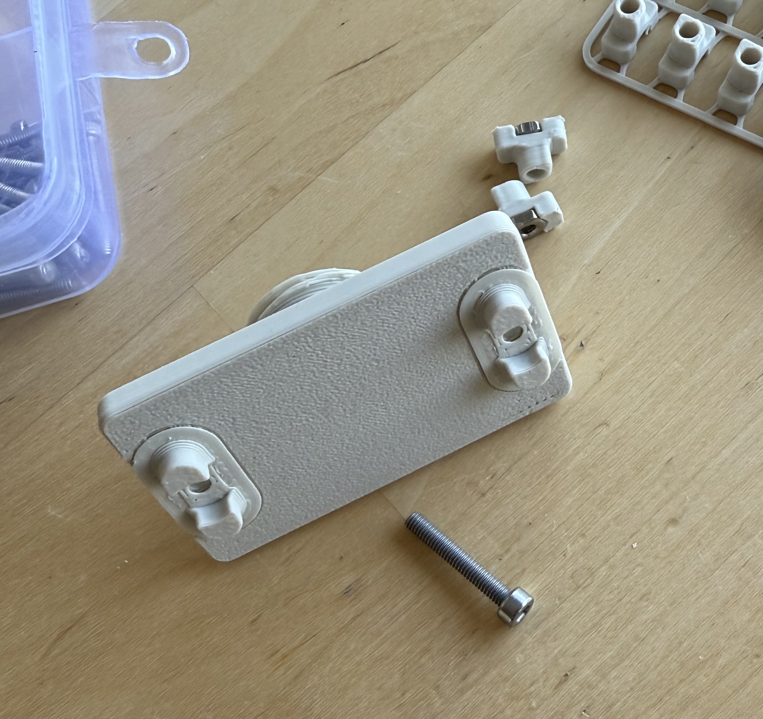
The front of the case has slots for ventilation (it gets warm) and the light sensor, and a guide for the LEDs. They prevent light bleed, so try to use a more opaque filament (such as PLA matte) for the case. The two 1.75mm holes above the LEDs can be filled with a piece of transparent filament to work as light pipes. I used darker translucent PETG to reduce the red led brightness.

(Might need to enlarge the holes slightly, but keep it tight, or apply a little glue.)
Links:
Additional Notes:
If your double sided tape allows the small inductor on the backside of LD2410 to touch metal shield of the ESP, you may hear a clicking sound. Sliding a small piece of paper in between should resolve this.
Updates
2025-11-06: Added DIN mount for the radar Base such that it can be mounted inside a utility panel. The DIN bracket is from https://www.printables.com/model/420009-din-rail-bracket-heat-insert-version-525mm-625mm/files .

2026-08-02: Updated the model to accomodate an IR Transmitter and Receiver. This allows using the sensor as an Infrared Proxy via HomeAssistant.