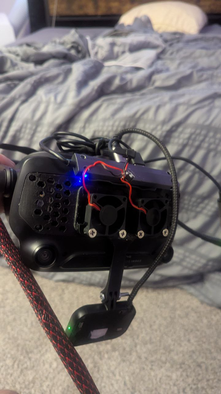
Valve Index Frunk/Big Screen Beyond: Face Tracking Mount
Obliczymy ostateczną cenę na podstawie wybranego pliku. Sprawdzisz ją i zaakceptujesz przed płatnością.
Zapisane na tym urządzeniu.

A frunk plastic replacement that has an extended mount for face tracking interfaces (uses standard m5 screws)
- Ocena
- 0 / 5
- Polubienia
- 6
- Pobrania
- 86
- Wydruki
- 0
- Wyświetlenia
- 900
- Oceny
- 0
Aktualizacja u źródła:
Informacje o modelu
- Źródło
- Printables
- Kategoria
- Virtual Reality
- Licencja
- Creative Commons — Attribution — Noncommercial — Share Alike
If you're here for a Valve Face Tracker Mounting solution that's nice and sturdy you've come to the right place! Just download the Frunk replacement, swap it for the current one, and then you're good!
However if you wish to assemble your own Face tracker using Project Babble Keep on reading!
------------------------------------
This is a collection of models I used to assemble a Babble face tracker. Using various models and tools all linked in this post.
-------------------------------------
== Disclaimer ==
I just ask if you use this to make a video, a remix, or any content teaching people how to do these steps you reference this post, and the associated posts I have linked in this document so all credit goes to all original creators and remixers!
=============
Hardware you need
3d printer
Project Babble Approved Components
https://docs.babble.diy/docs/hardware (Babble Documentation where all information can be found for the parts)
The parts I used:
XIAO-ESP32S3-Sense Board from Seeed Studio
This board is capable of Wireless and Wired, In this tutorial I will be using a wired connection.
OV2640 160° FOV IR / Night Version (850nm) (found on AliExpress)
Make sure you get the shorter length one with the larger FOV (160)
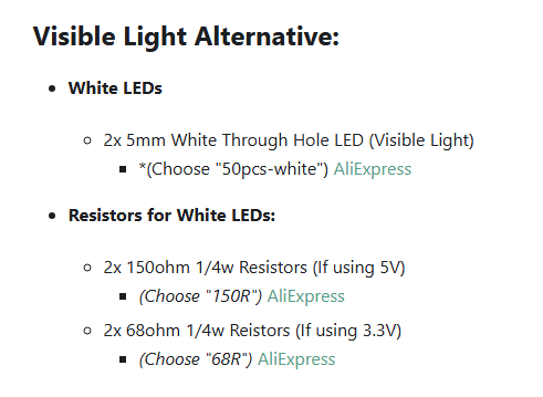
I did the Visible Light Options from the Babble documentation and picked the 68ohm wired to the 3.3v
Additional Tools/Parts
Generic 26 AWG wiring (I recommend getting colors to keep things straight)
Soldering Iron
I got one from Menards for about $25 and it came with Soldering.
USB C Cable (I recommend a right angle one)
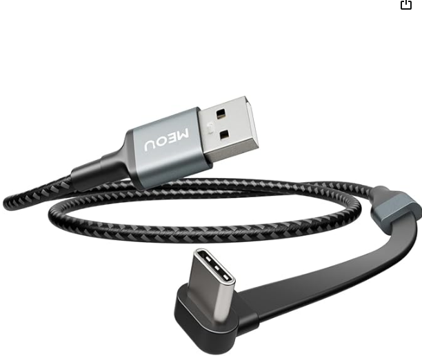
USB C to C Option for BsB: https://www.amazon.com/dp/B0DQ8B8PFR?smid=AMPV5JPIE48RB&ref_=chk_typ_imgToDp&th=1
m5 Screws with nuts
Heat Shrink Tubing or Electrical tape
Zipties (optional)
Software you will need to download
Eye Track VR Firmware flashing tool
This is for flashing the ESP32 board
NOTE: I used the USB only flash, the ESP32 board recommended above is capable of wireless and wired, I choose to do wired since this is primarily to be used with Index.
Project Babble
VRCFT (VRChat Face Tracking)
(Install the Babble FT module in the Modules section of the app)
Printing
When printing you'll likely need to print the following:
Frunk Mount
If you want speed, go with the usual supports, it'll be much faster but the support material is harder to get off
If you don't mind waiting go with organic supports but it will take longer and use less support material saving you money.
Seeed Studio shell Left and right
Face Tracker Extension
(If you want to do your own lighting solution you can ignore this next part)
LED Snap-in Mount
This is the LED Snap-In I made from scratch. I know is loose on both the board shell and the LED mounts, so feel free to modify the holes or change it as needed!
The Default hole size for this is 5 mm
5 mm LED Mount x2
Assembly
Following the wiring guide for the Babble Face Tracking, wire your lighting how you wish.
Once wired, Change the default camera that came on the ESP32 board to the 160 camera.
you can do this by lifting the little plastic flap and sliding out the camera gently
Then put the new camera in and then put the flap back down
DO NOT FORCE PULL OR PUSH! It should be nice and easy
Flash then test the firmware of the camera
Open Eye Track VR Firmware Flash tool and select the proper firmware you want
in this case USB for the ESP32 Seeed Studio board.
Take note of the COM port your cam is connected to
Open project babble and enter the COM port of your Camera and you should see what the camera sees. (Repeat previous steps as needed)
If working, Unplug the camera and continue to the next step.
Assemble both halves of the Camera Shell around the ESP32 board taking extra care to not squish the camera's cable.
Plug in the USB-C Cable with the cord facing backwards and then Cord Manage and Zip Tie as needed
Once the Camera Module is assembled and cable managed Unscrew the 4 screws holding the original Frunk in the Index in place and save the screws for the next step
Feed the USB cable through a hole in the frunk and then plug it into the USB slot
Place the New Frunk mount in place and screw it down
Using M5 Screws finish the assemble using the extender if needed
Optional: snap in the LED Snap-in mount to the bottom of the ESP32 Shell and then the associated 5mm LED snap in's
NOTE: Plug in the USB C and make sure the SNAP in component is flipped the right way to not interfere with the USBC cable
DONE!
My Setup Fully Assembled

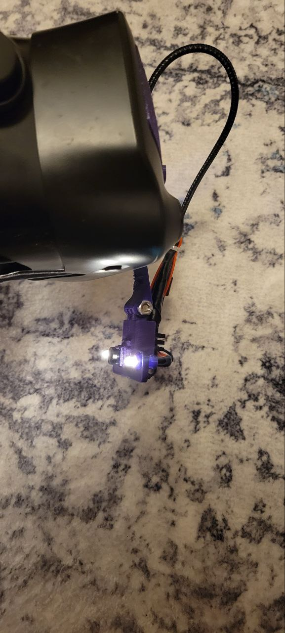

My friend Wally and his setup using the Frunk