
1 / 5
Case fo USB-C PD Trigger Board Power Supply
Zamów wydruk tego modelu
Obliczymy ostateczną cenę na podstawie wybranego pliku. Sprawdzisz ją i zaakceptujesz przed płatnością.
Zapisane na tym urządzeniu.

Use this case to enclose your USB-C PD Trigger Board and use it as a power supply
- Ocena
- 4,5 / 5
- Polubienia
- 233
- Pobrania
- 594
- Wydruki
- 2
- Wyświetlenia
- 3943
- Oceny
- 2
Aktualizacja u źródła:
Informacje o modelu
- Źródło
- Printables
- Kategoria
- Tools
- Licencja
- Creative Commons — Attribution — Share Alike
SzczegółyPliki (5)Wydruki i komentarze (Wydruki: 2) (Komentarze: 5)Remiksy (0)Kolekcje (305)Powiązane
BOM
| Part | # | Photo |
|---|---|---|
M2x10 or M2x12 screws, self-tapping, countersunk | 4 |  |
USB-C PD Trigger Board with DIP Switches | 1 |  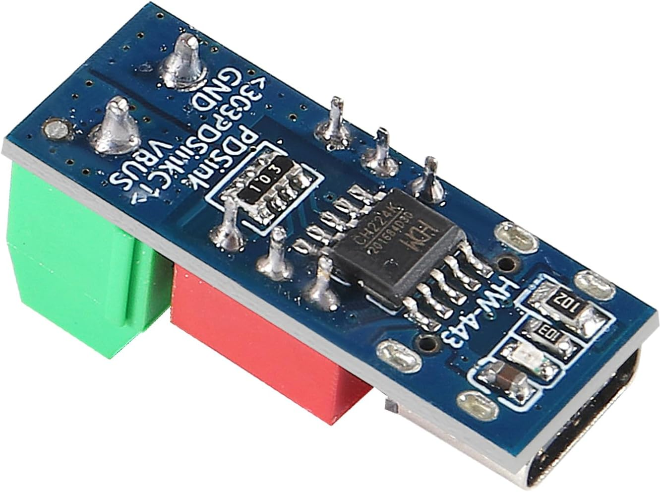 |
Printing
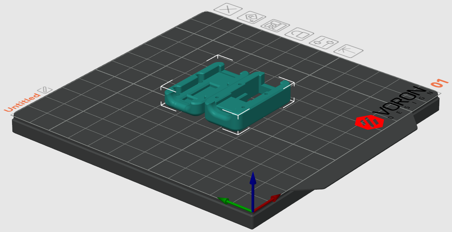
No supports needed. Use 2 or 3 walls. 15% infill should be fine.
Assembly
| Step | Photo |
|---|---|
| Use flush cutters to cut the through-hole pins of the bottom of the board (don't remove the chip or other SMD components). |  |
| Place the board into the case bottom. | 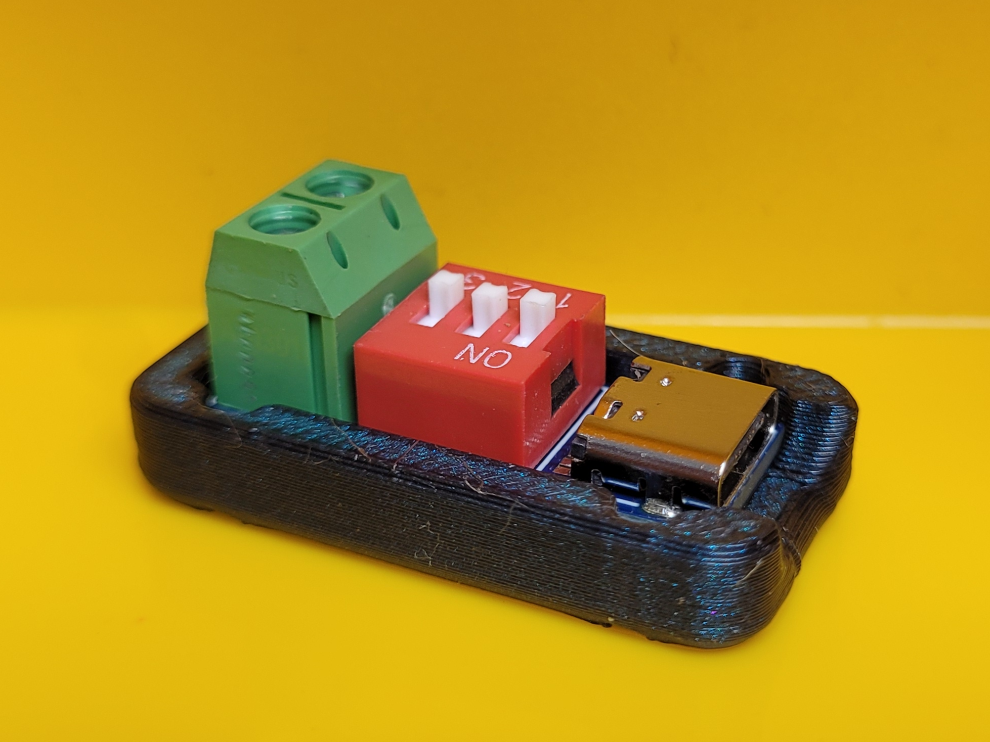 |
| Set the case top into place. | 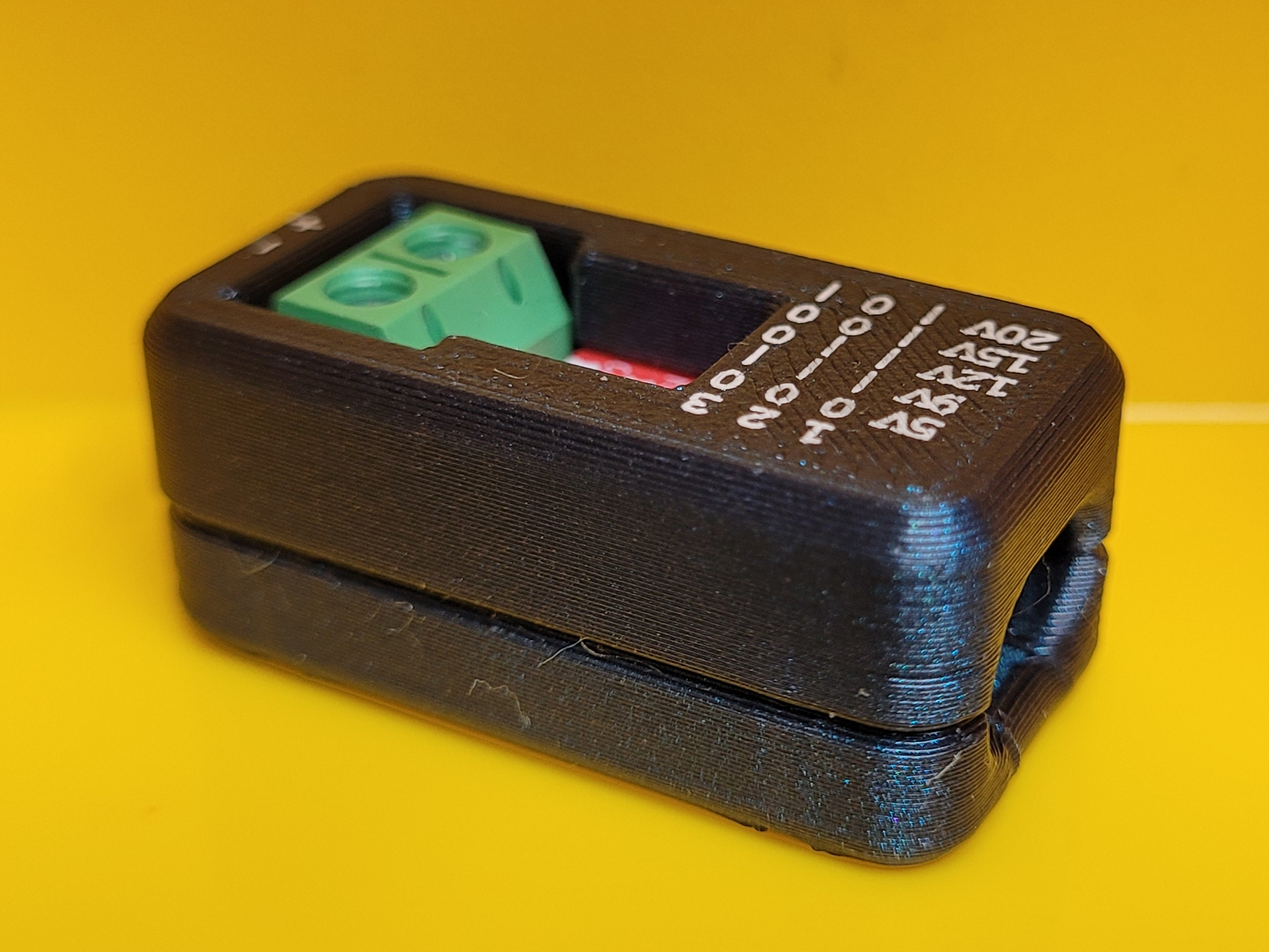 |
| Screw in the four M2 screws. | 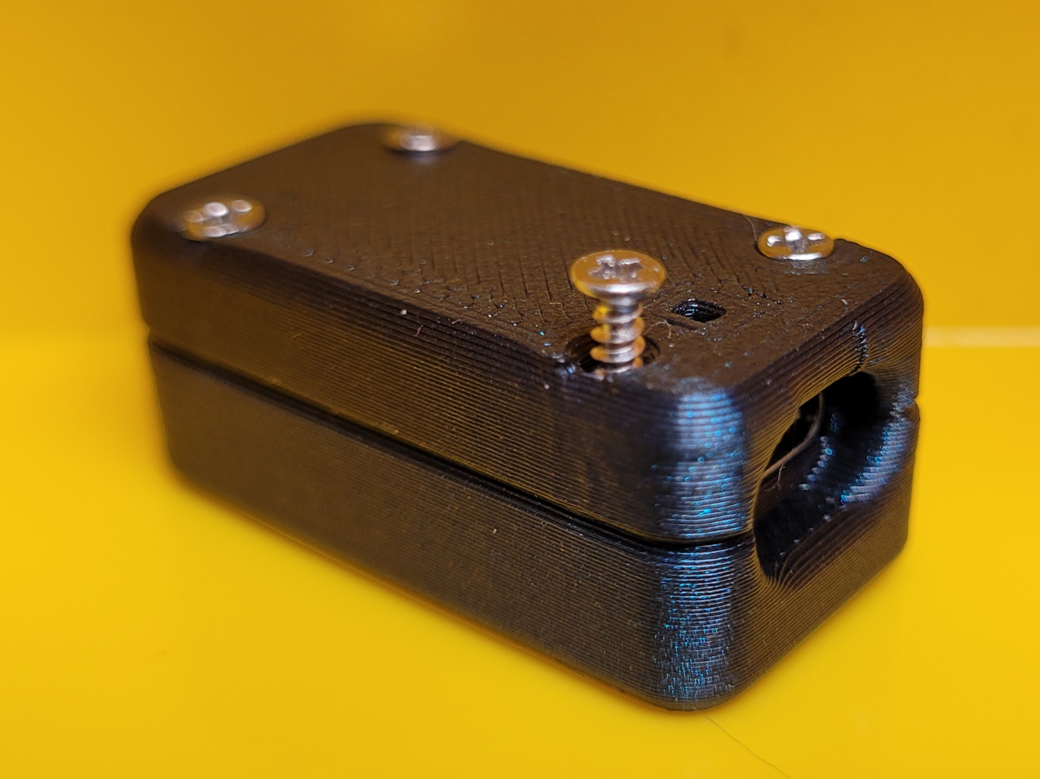 |
| [Optional] Embellish your case with a laser engraving or a label! | |
| Configure your desired voltage. |
I've found that many of these boards have different pin settings so make sure you double check these with a multimeter. For mine, here's the configuration
| Voltage | p1 | p2 | p3 |
|---|---|---|---|
| 5V | 0 | 0 | 0 |
| 9V | 1 | 1 | 1 |
| 12V | 1 | 1 | 0 |
| 15V | 1 | 0 | 0 |
| 20V | 1 | 0 | 1 |
CAD
Feel free to take a look at the CAD on Onhape. You should be able to fork from my design, or export to use in your CAD program of choice.