
1 / 5
Case fo USB-C PD Trigger Board Power Supply
Order a print of this model
We calculate the final price from your selected file. You review and accept it before payment.
Saved on this device.

Use this case to enclose your USB-C PD Trigger Board and use it as a power supply
- Rating
- 4.5 / 5
- Likes
- 233
- Downloads
- 594
- Makes
- 2
- Views
- 3,943
- Reviews
- 2
Updated at source:
Model information
- Source
- Printables
- Category
- Tools
- License
- Creative Commons — Attribution — Share Alike
BOM
| Part | # | Photo |
|---|---|---|
M2x10 or M2x12 screws, self-tapping, countersunk | 4 |  |
USB-C PD Trigger Board with DIP Switches | 1 |  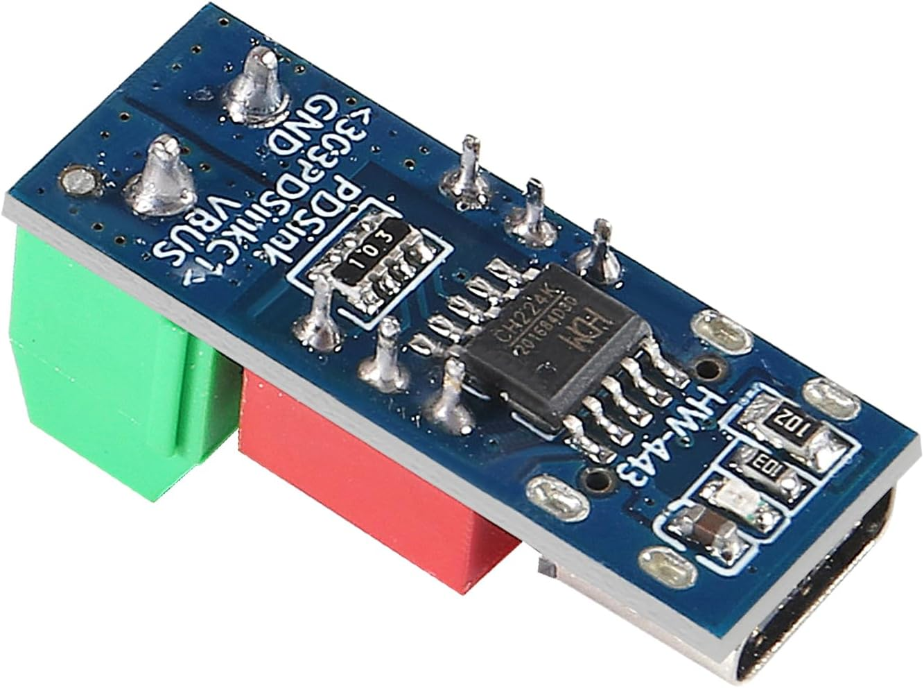 |
Printing
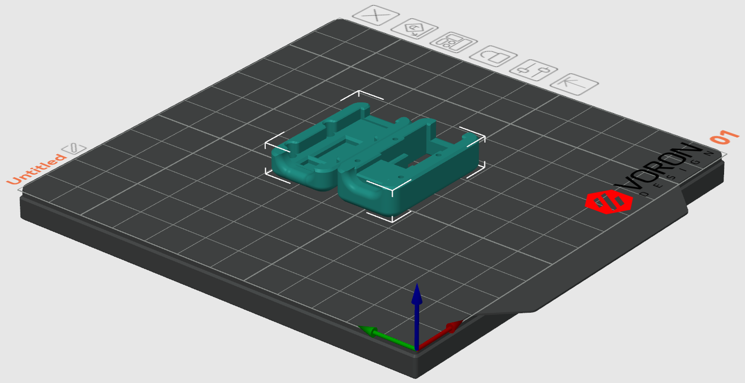
No supports needed. Use 2 or 3 walls. 15% infill should be fine.
Assembly
| Step | Photo |
|---|---|
| Use flush cutters to cut the through-hole pins of the bottom of the board (don't remove the chip or other SMD components). |  |
| Place the board into the case bottom. | 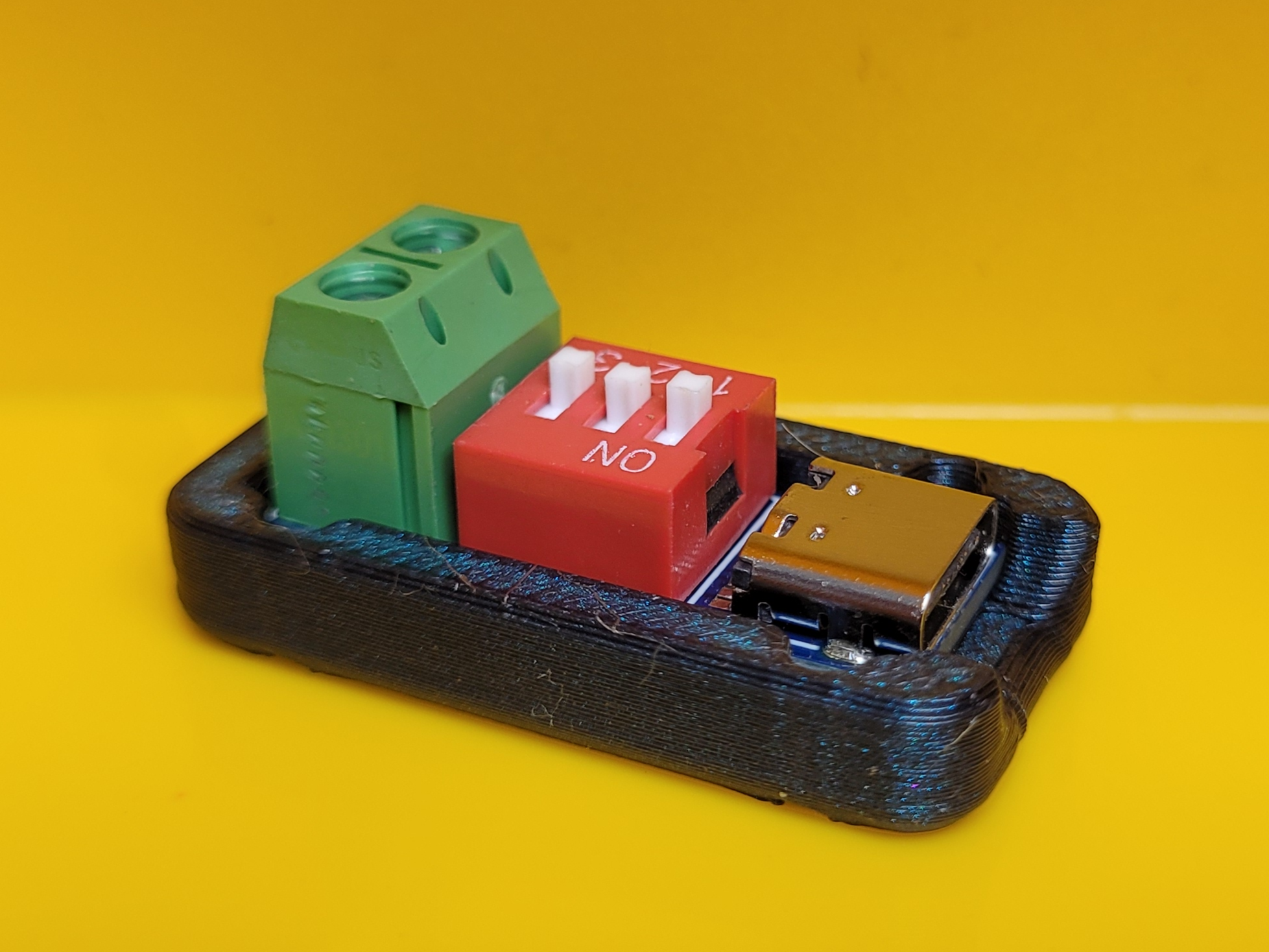 |
| Set the case top into place. | 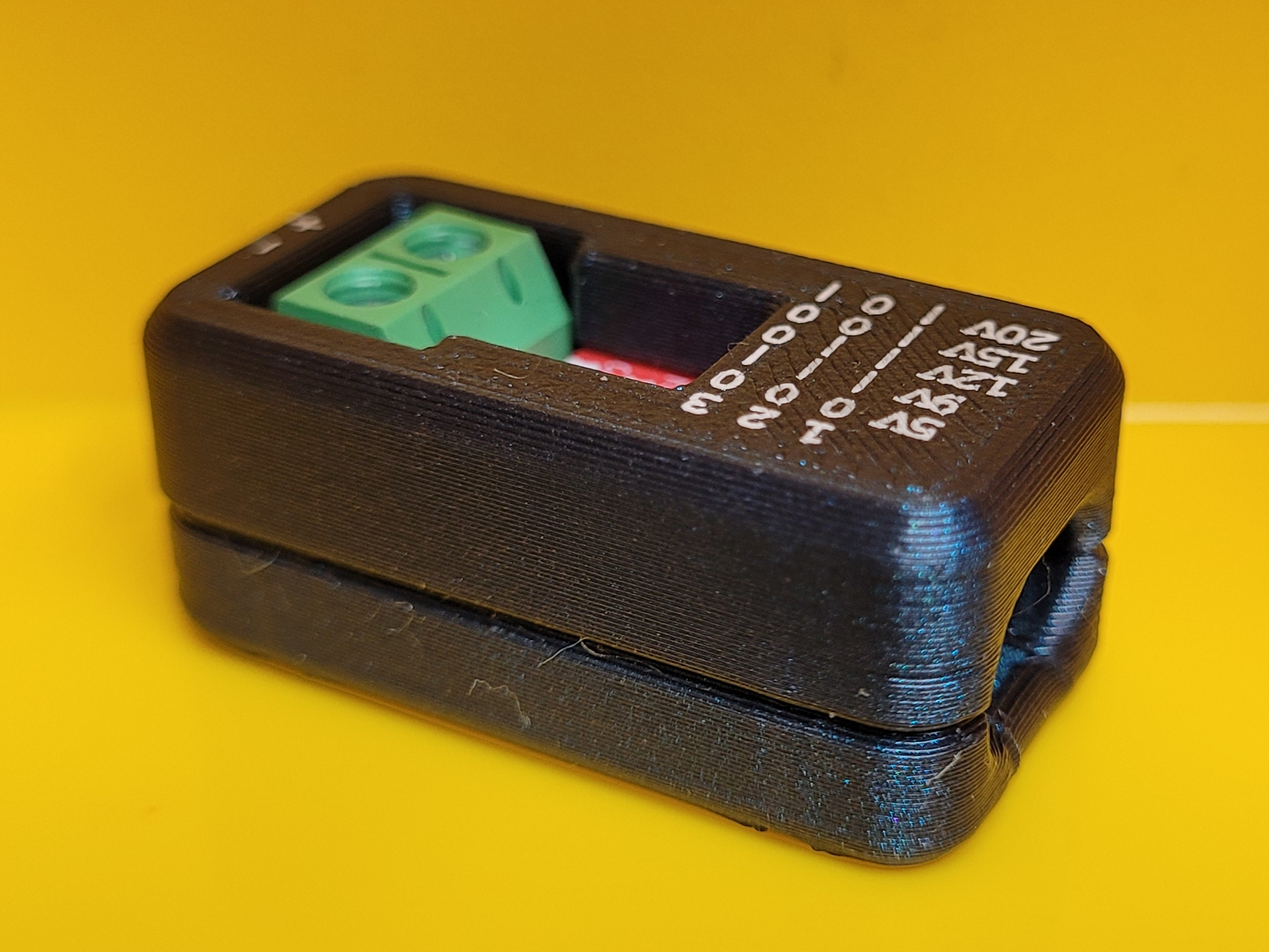 |
| Screw in the four M2 screws. | 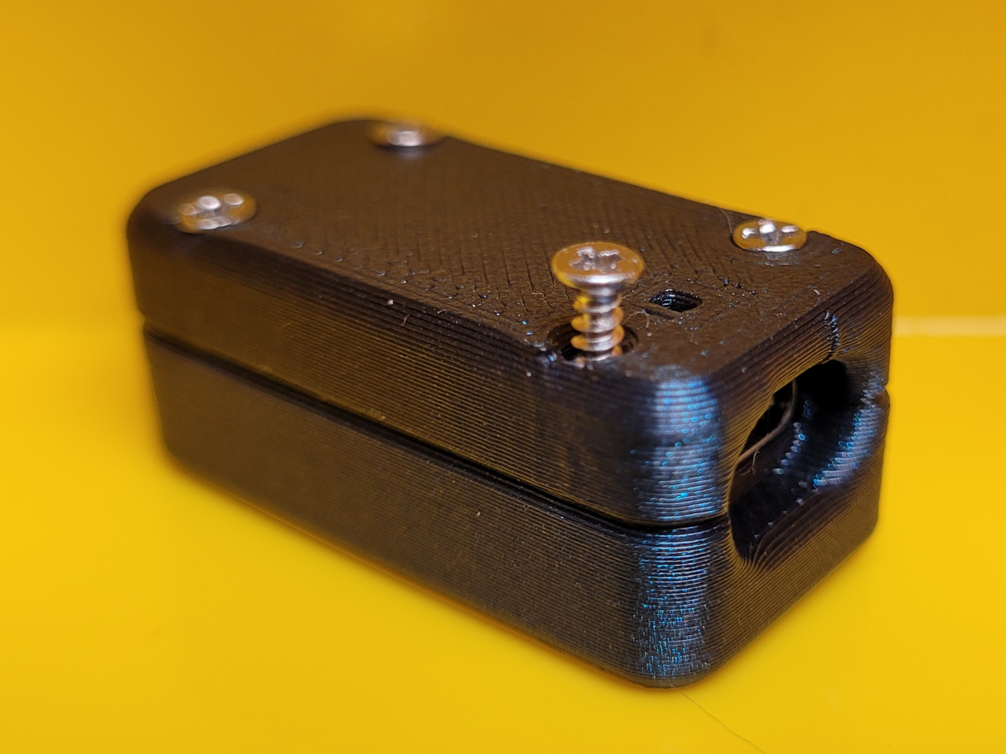 |
| [Optional] Embellish your case with a laser engraving or a label! | |
| Configure your desired voltage. |
I've found that many of these boards have different pin settings so make sure you double check these with a multimeter. For mine, here's the configuration
| Voltage | p1 | p2 | p3 |
|---|---|---|---|
| 5V | 0 | 0 | 0 |
| 9V | 1 | 1 | 1 |
| 12V | 1 | 1 | 0 |
| 15V | 1 | 0 | 0 |
| 20V | 1 | 0 | 1 |
CAD
Feel free to take a look at the CAD on Onhape. You should be able to fork from my design, or export to use in your CAD program of choice.