
INA3221 Voltage\Current Sensor for Home Assistant v1.1
Obliczymy ostateczną cenę na podstawie wybranego pliku. Sprawdzisz ją i zaakceptujesz przed płatnością.
Zapisane na tym urządzeniu.

Informacje o modelu
- Źródło
- Printables
- Kategoria
- Electronics
- Licencja
- Creative Commons — Attribution — Noncommercial — Share Alike
A 3-channel voltage and current sensor for Home Assistant using ESPHome.
- Could for example be used as a battery or solar panel tester that will graph everything out in HA.
- Basically 6 multimeters in one unit.
- Can also be used standalone with custom code.
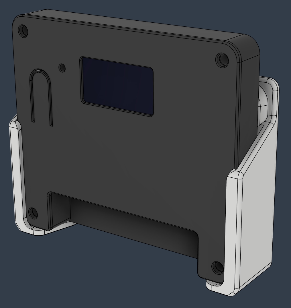
- Comes with a wall mount that also works as a stand with long screws in the top holes.
- Stand prints standing up.
- OLED screen is optional.
- Top needs 4x M3 10mm (max) screws.
- Code could not be pasted in, so it's in the text file. Code is for the S3.
- v1.1 case should fit the standard INA PCB board.
Compatible with multiple “Supermini” type esp32's, and should also fit the XIAO series from SeeedStudio and similar Waveshare C3\S3. I'm using the Supermini S3, which also has a button and addressable RGB light on the lid, and can be used in HA. I used some clear filament as a light pipe for this LED, after drilling out the hole with a 2mm bit. The end can be heated so it mushrooms on the inside, so it can't be pulled out.
- Supermini S3 button is on pin 0. C3 has it on pin 9.
- C3 has a simple LED on pin 8.
- S3 has both an addressable RGB and simple LED on pin 48. Can only use one.
It uses an INA3221 board from a UK store on Tindie. This is available with several resistors that gives different current limits and resolutions. Read the documentation for that. This is not my board. I'm using the 0.01 Ohm, which has theoretical limit of 16A, but is limited to around 5A according to seller.
- This board was chosen because the larger cheaper board might show up in a bad version where all the channels are linked together, so you can't use different power supplies on them. The Tindie board is more expensive but has guaranteed separated channels, and has multiple resistor options.
- Measures up to 26V (high-side).
- Should be able to mix resistors as well, so you could have a low current, high res channel.
- Code needs to be adjusted if you use other resistors.
It uses 7x inline Wago 221 quick connectors (7th is for grounding the board to whatever you're measuring). These and the boards needs to be glued down to the frame. Don't use silicone for this as it's very corrosive unless it's neutral cure. I used MS polymer.
Also added a top for an OLED screen to it. It's a RAK1921, but it may fit a regular SSD1306 0.96", 128x64, I2C screen. The code is very basic so it just shows voltage\current on the 3 channels.
I have more screens on the way so I might add something for a larger one later that can fit more info, like the missing wattage. Maybe others are able to make more advanced code that shows a graph on screen.
-----------------------------------------------------------------------------------------------------------------------
 |  |
Changelog:
v1.1
- Added 2mm vertically extended case to fit the standard INA sensor PCB (38x32.3mm).
- Updated the code a little, with a better "Roboto" font.
- You can now swap between different screens using the button on the SuperMini S3, and maybe C3.
