
Trailer for 3DSets Mogster
Obliczymy ostateczną cenę na podstawie wybranego pliku. Sprawdzisz ją i zaakceptujesz przed płatnością.
Zapisane na tym urządzeniu.
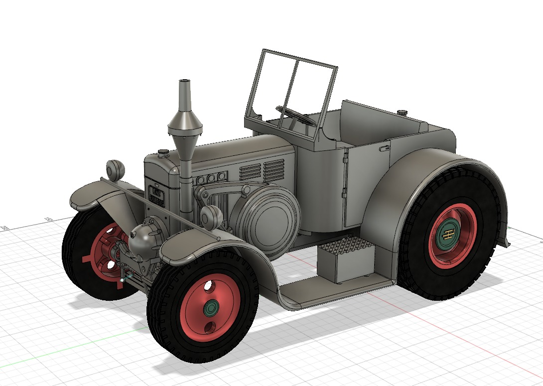
An (unofficial) Trailer for the 3dSets Mogster Truck. Including tipper functionality (requires Mogster Tipper files)
- Ocena
- 0 / 5
- Polubienia
- 10
- Pobrania
- 26
- Wydruki
- 0
- Wyświetlenia
- 112
- Oceny
- 0
Aktualizacja u źródła:
Informacje o modelu
- Źródło
- Printables
- Kategoria
- RC & Robotics
- Licencja
- Creative Commons — Attribution — Share Alike
Summary
You can use this trailer in four different "configurations":
standalone trailer, no tipping, no lights - just a basic trailer
tipper, no lights - uses the same tipping mechanism as the Mogster
trailer, no tipping, lights
tipper with lights - you can tie the lights into your Mogsters light system to have blinkers and rear end lights.
To use this trailer with your Mogster you need the correct trailer hitch which you can find here: 3DSets Mogster Trailer Coupling. As well as the coupling, the trailer also uses a spring within the coupling assembly to dampen shock loads. You don't necessarily need it but I recommend using it. Another thing I have to add in the beginning: I haven't tested the load capacity yet. It can load the Mogster but I wouldn't try to tip this kind of weight or you would risk damaging the model. The leaf springs can either be printed or replaced with metal springs like these.
For configuration 1 you only need to source the screws, bearings and tires listed in the BOM. The hinges are held on by filament or small diameter wire, same as the tipper bed of the Mogster.
For configuration 2 you also need to source another linear actuator and an ESC which can be housed in the air tank. You can either feed this from a separate battery and only route the signal wire to the mogster through the "'Frame Rear End' with holes for 1x3 Pin Dupond- (Servo-) connector" (coupling) or feed it directly from the Mogsters battery.
For configuration 3 it's easiest if your Mogster already includes a light system. You can tie the rear lights and blinkers direcly into the main lighting system. Als you'll be needing at least 4 pins (GND, blinker left, blinker right, rear lights) you'll need to use "'Frame Rear End' with holes for 2x3 Pin Dupondconnector (two Servo connectors next to each other)" for your coupling.
For configuration 4 it's just a combination of configuration 2 and 3, this is the one I made and is shown in all the pictures. I also used the 2x3 Pin connector for lights and power which I got from the Mogsters battery so the trailer can be completely "dumb".
Required Parts
Due to IP-laws I cannot share the tipper mechanism directly. However if you have already purchased the Mogster Tipper you just need to reprint the following files and screw them to the trailer:
Tipper Piston Bed
Tipper Piston Hinge
Tipper Piston Rod
The ways should be greased to ensure proper functionality - just like the tipper bed on the mog. If you don't own the mogster files for the tipper variant you can still use this trailer as a "static" variant in configuration 1.
Printing
I split the files into bed-sized chunks grouped by colour and material. I used PLA for all parts exept the "TPU Bumpersaver" which quite litteraly saved my bumper from being torn of offroad quite a few times now. Parts are already oriented in the way I printed them. I also included the full assembly as a step-file as well as the 3mf of all the beds combined into one file (Prusaslicer unforunately only allows for up to 9 beds per project file, so some "beds" are not visible).
Electronics
I made a quick schematic to visualise the electronics on the trailer in EasyEDA, nothing too complicated:

Pins 1 and 3 of CN2 were then connected to the blinker pins of my light system in the mogster.
Foot/Support leg
The support foot should be assembled as shown below. First you add a drop of Locktite on the M5x60mm screw before you insert it into SupportFoot_Housing. Then, using the SupportFoot_MountingTool, add the first M5 nut (left side in diagram). Screw it in but don't tighten it. The screw should freely spin without falling out of the housing. Wait for the Locktite to fully harden. Add the SupportFoot_Handle, then you can just screw the SupportFoot_Leg into place by turning the handle.

Thats it ;)
If you have any more questions, feel free to leave a comment or message me :)
Happy printing!
Changelog:
02.11.2026: Added SupportFoot_MountingTool.stl and .stp. Added section "Foot/Support leg"