
1 / 12
Prusa Mini+ CFD-optimized Fan Duct v2
Zamów wydruk tego modelu
Obliczymy ostateczną cenę na podstawie wybranego pliku. Sprawdzisz ją i zaakceptujesz przed płatnością.
Zapisane na tym urządzeniu.

CFD-optimized fan duct (v2) with 3 outlets, based on the original Prusa Mini+ X-Carriage (fan duct).
- Ocena
- 4,421 / 5
- Polubienia
- 261
- Pobrania
- 1219
- Wydruki
- 40
- Wyświetlenia
- 5434
- Oceny
- 38
Aktualizacja u źródła:
Informacje o modelu
- Źródło
- Printables
- Kategoria
- Prusa Parts & Upgrades
- Licencja
- Creative Commons — Attribution — Noncommercial
SzczegółyPliki (2)Wydruki i komentarze (Wydruki: 40) (Komentarze: 88)Remiksy (6)Kolekcje (405)Powiązane
Updates:
01.02.2023
- improved airflow path for normal version
24.01.2023
- Pinda probe was contacting fan duct→ bigger indentation in fan duct
- optimized airflow
23.01.2023
- added new model for better flow with low placed printingnozzles and silicon sock
01.2023
- removed material to avoid collision with z-carriage
- already first successfull makes → see comment section
Testing is still required regarding:
- collision with heatbed screws
- collision with heatbed cover
- silicon sock fit and airflow (does silicon sock block airflow)
- bridging test
- printability of the model (air splitters, overhangs, duct openings)
Testing is welcome! I will try to include any feedback.
Version 2.0 Improvements
- Improved alignment of side fan ducts for more accurate nozzle targeting
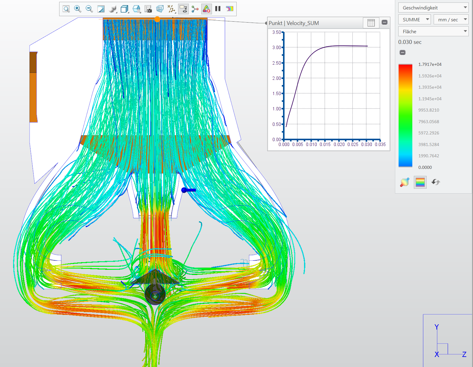
- Further reduction in air resistance through the fan duct (→faster exit speed, same volumetric flow as Prusas original design)
- No more collisions with heatbed cover or centering screws at the back of the heatbed
- More precise CFD analysis and optimized outlet alignment
- Additional room made for silicon sock (cannot guarantee results as no silicon sock available for testing)
- Surface imperfections from previous model retouched (but also some new “impferfections” added to make sure everything fits^^)
Version 1.0:
Upgraded Prusa Mini Fan Duct
- Two additional nozzles to cool the component from three sides
- Optimized for minimal air resistance while maintaining the same volumetric flow as the original nozzle (similar load for the fan)
- No additional support structures or modifications to other components needed (PINDA, Heatbedcover)
- Nozzle designed to avoid overlap with other parts (Siliconsock, Heatbedcover, Heatbed screws, Pinda holder)
- Material with higher glass transition temperature recommended to prevent melting of fan duct ends
(ideal) Printing Parameters
- Layerheight: ≤0.2mm
- Linewidth: 0.45mm
- minimum feature size (cura): 0.07 mm → for optimal air splitter bridging
- Material: PETG, ASA, ABS, other higher temperature materials
- There are important bridges (air splitting), ideally use Arachne for ideal wedge form of the splitters and slower bridging speed.
- Do not print with more then 20% infill (else too stiff and too high pressure on linear bearings)
Written using ChatGPT^^