
1 / 7
Arduino Nano humidity meter project - EVERYTHING is explained
Zamów wydruk tego modelu
Obliczymy ostateczną cenę na podstawie wybranego pliku. Sprawdzisz ją i zaakceptujesz przed płatnością.
Zapisane na tym urządzeniu.

Arduino Nano + 128x32 i2c OLED display
- Ocena
- 0 / 5
- Polubienia
- 9
- Pobrania
- 42
- Wydruki
- 0
- Wyświetlenia
- 691
- Oceny
- 0
Aktualizacja u źródła:
Informacje o modelu
- Źródło
- Printables
- Kategoria
- Accessories
- Licencja
- Creative Commons — Attribution — Noncommercial
Hello World!
In here you will find:
- What you'll need
- How to assemble the parts
- Wiring instructions
- Code for Arduino + instructions
Let's go..
What you need:
- Arduino nano or clone (amazon - https://shorturl.at/egjK9)
- OLED display 128x32 i2c SSD1306 (amazon - https://shorturl.at/hoLX0)
- Humidity sensor DHT11 or DHT22 or BOSCH (DHT11 amazon - https://shorturl.at/lwyPV)
- Generic USB A to USB-C or MicroUSB ( depending on your arduino nano) cable
- Dupont cables:
- Female to Female - 7x (3x for DHT, 4x for OLED)
Disclaimer: Those are NOT affiliate Amazon links, they are generic shortened links.
!LOOK AT ALL THE PHOTOS ATTACHED IN FILES FOR CLARITY DURING INSTRUCTIONS!
3D Printed parts explanation:
- OLED 1 + OLED 2 - case for the display to be seated
- Nano 1 and Nano 2 - case for Arduino Nano with cooling holes
- Stand - m3x5 screw is holding the DHT11 seated
- The parts itself are meant to be glued / double-side taped to any surface you want
- All parts labeled 1 and 2 are meant to be glued together after placing the components inside

Instructions for boxes:
- (If OLED pins are marked on the bottom) Push OLED display to 3D part named OLED 1; otherwise do step 2 first and note pins-colors pairs (Note that one cutout is longer - match the orientation)
- Connect 4 cables to pins (now irrelevant how, write down colors and pin pairs)
- Grab part OLED 2 and push the cables from the display through the hole (from inside to outside) and glue both parts together (put glue on the 2 mm thick edges of one part)
- Grab the part named Nano 1 and push the cables from the OLED sensor through a circular hole (from outside to inside)
- Now connect wires to the DHT/BOSCH sensor and push them through the part named Nano 1 from the previous step (the cables from DHT and OLED should run through the same hole) (from outside to inside)
- Now connect all cables from DHT and OLED to the Arduino, How exactly is written in the chapter below (if you used different sensors or Arduino, everything can be googled in seconds)
- Push the Arduino with the top (where LEDs are) first to the part named Nano 2 (the one with holes for cooling) - Note the orientation for the charging cable
- Connect a charging cable through the designated hole in the part Nano 2
- Glue together part Nano 1 and Nano 2
- Grab the part named Stand, and place the sensor on top (the orientation doesn't really matter). Screw the m3x5 screw through the hole inside the board the DHT is on and to the Stand. Make sure it doesn't really move after but don't tighten it too much!
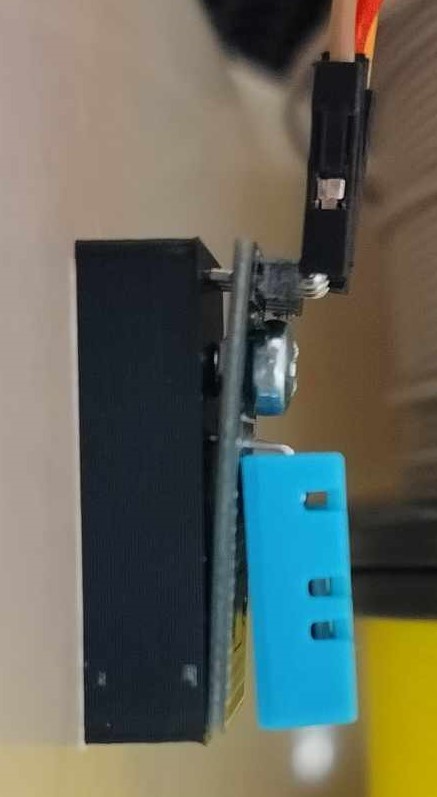
11. Glue or double-side tape the boxes containing Nano and OLED and the Stand part to any surface
12. Connect to the computer and follow the code section of this guide
How is it connected?
- DHT11
- - to GND
- + to VCC, 3V3or ICSP 5V
- middle one to Data pin (in code defined, default is 5)
- OLED
- VCC to VCC, 3V3 or ICSP 5V
- GND to GND
- SDA to A4
- SCL to A5
Code (might not be the best, but works regardless):
- Setup:
- Install Arduino IDE and configure COM port and board type
- Install libraries:
- SSD1306 by Adafruit (and its dependency - Adafruit GFX)
- DHT sensor (https://github.com/adafruit/DHT-sensor-library)
- Wire
- Code: https://pastecode.io/s/j2n5cw37
- If the OLED doesn't work, maybe the address is different - (https://randomnerdtutorials.com/guide-for-oled-display-with-arduino/)
POWER UP AND IT IS DONE!