
USB-C Solder Fume Extractor 80mm (Noctua)
Obliczymy ostateczną cenę na podstawie wybranego pliku. Sprawdzisz ją i zaakceptujesz przed płatnością.
Zapisane na tym urządzeniu.

A USB powered soldering fume extractor for an 80x25mm 12V fan / Noctua NF-A8
- Ocena
- 5 / 5
- Polubienia
- 46
- Pobrania
- 121
- Wydruki
- 1
- Wyświetlenia
- 1028
- Oceny
- 1
Aktualizacja u źródła:
Informacje o modelu
- Źródło
- Printables
- Kategoria
- Electronics
- Licencja
- Creative Commons — Attribution — Share Alike
This is a compact USB-C solder fume extractor that uses an 80x25mm 12V PC fan. It's intended for people who have to do the odd soldering job every now and then and want something that doesn't occupy too much space when not in use.
It's designed for the Noctua NF-A8 (with noise dampers removed) but should work with other 80x25mm fans as well. It uses a fan grill design inspired by the Seasonic Prime XT-1600 Noctua Edition power supply (based on this image).

Here are some of the key features:
- Compact
- Magnetic back cover to easily access the filter and electronics
- Uses only two types of screws
- Simple 3-part design
- Detailed, step-by-step assembly instructions

Tools & Materials
- 3mm hex driver
- 1.5mm hex driver
- Multimeter (for voltage adjustment)
- Soldering iron, solder, and flux
- Wire stripper
- Heat-set insert press (or use soldering iron)
- Superglue
- Scissors or blade
Required Hardware
| Qty | Description | Sourcing |
|---|---|---|
| 4 | M3x30mm or 35mm Socket Head Cap Screw | Aliexpress |
| 2 | M2.5x6mm Button Head Cap Screw Alternatively, self-tapping screws should work as well. | Aliexpress |
| 4 | M3 x D4.6 x L4.0 Heat-Set Insert | Aliexpress |
| 8 | 6x2mm Neodymium Disc Magnet (N45 recommended) | Supermagnete, Amazon DE (N35) |
Electronic Components
 | 80x80x25mm 12V PC fan (I used Noctua NF-A8) Most 80x25mm fans should work. It doesn't matter if it has 3 or 4 wires as you only need two. |
 | Step-Up Voltage Regulator / DC-DC Boost Converter I used a MT3608 boost converter but any voltage converter that can boost 5V to 12V and support the current required by the fan will do. |
 | USB-C Female Socket with Mounting Chassis This connector has the R1 and R2 501k resistors already installed so it works with PowerDelivery chargers as well. Sourcing: Aliexpress (Color: A) |
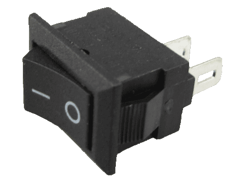 | Mini Rocker Switch 15x10.5mm |
 | Black and Red 24 AWG Wire Thicker wire is fine too. I don't know the exact length needed but it's not much. Maybe ~30cm each. |
 | Activated Carbon Filter ~10mm thick (up to 13mm) Sourcing: Amazon DE |
Printing
Print the parts in the original orientation. All STLs are pre-rotated into the right orientation for printing.
- Material: PETG, PLA, ASA, etc. (anything non-conductive)
- Extrusion width: 0.4 or 0.45mm
- Layer height: 0.2mm
- Perimeters: 4
- Infill: 20%
- Supports: no
Assembly Part 1
During this assembly, do not install any of the electronic components yet.
Step 1: Insert heat-set insert into Filter holder
Using a heat-set insert press or soldering iron, press the heat-set inserts into the Filter Holder until they are flush with the printed part.

Step 2: Insert magnets into Filter Holder
Add a small drop of superglue into the magnet holes on the other side of the Filter Holder. The magnets are press-fit. If necessary, use a tool, such as a vise or parallel jaw pliers to push the magnets into the holes.
Pay attention to the polarity. The polarity must face in the same direction for all magnets.

Step 3: Insert magnets into Lid
Using the same method as above, push the magnets into the Lid with a small dot of superglue.
Important: The Lid attaches to the magnets on the Filter Holder. So the magnet polarity must now face the opposite way.

Step 4: Install fan on Main Body
Cut off the fan connector. Trim off the fan data wires and leave only the positive and negative power wires (red and black if using 3-pin Noctua fan). Read the documentation for your fan if you are not sure.
Remove the anti vibration pads from the fan if using the Noctua NF-A8.
Place the fan on the Main Body with the logo side facing the back of the device, as most fans blow air toward the side with the logo. If your fan has airflow direction arrows on the frame, use them to confirm the correct orientation. The airflow should blow toward the filter that will be installed later.

Step 5: Install Filter Holder
Place the Filter Holder behind the fan. Pay attention to the debossed “B” on the Filter Holder. It should be facing downwards.
Push the M3x30mm screws through the front of the Main Body and screw them into the heat-set inserts on the Filter Holder. Do not over tighten the screws to the point where it compresses the fan. Just finger-tight is sufficient.

Electronics Wiring
Here's an overview of the wiring of the electronic components.

Step 1: Rocker switch preparation
Solder approximately 7 or 8cm of red wire onto each leg of the mini rocker switch.

Step 2: Install rocker switch
Push the rocker switch, along with its wires, into the hole on the front of the Main Body until it clicks in place.

Step 3: Wiring power input
Solder one of the red wires from the rocker switch to the VCC pin on the USB connector.
Solder the other red wire from the rocker switch to the VIN+ pin on the boost converter.
Solder a length of black wire from the GND pin on the USB connector to the VIN- pin on the boost converter.

Step 4: Adjust boost converter voltage
Plug a USB power source into the USB connector and set the rocker switch to the ON position.
Using a multimeter set to DC voltage mode, hold the red probe against the VOUT+ and the black probe against the VOUT- pin on the boost converter. Do not short-circuit the board while using the multimeter.
Adjust the little screw of the potentiometer until the voltage on the multimeter reads 12V.
Remove the multimeter, switch the rocker switch back to the OFF position, and unplug the power source.

Step 5: Wiring the fan
Solder the positive wire of the fan onto the VOUT+ pin on the boost converter.
Solder the negative wire of the fan onto the VOUT- pin on the boost converter.
Test the wiring: Plug the power source back into the USB connector and set the rocker switch to the ON position. The fan should now spin.
If the fan spins as expected, turn everything off again and carefully fit the electronic components into the electronics compartment. You can now turn off your soldering iron. If wires are a bit long you can neaten them up with zip ties.

Step 6: Attach the USB connector to the Main Body
Position the USB connector in the designated groove inside the electronics compartment. Then, using the M2.5x6mm screws, fasten the USB connector to the Main Body.
If desired, you can optionally hotglue the USB connector and boost converter to the walls inside the electronics compartment.

Assembly Part 2
Step 1: Cut filter to size
Place the Filter Stencil on a carbon filter sheet and cut along the stencil to cut the filter to the right size.

Step 2: Attach Lid
Place the carbon filter piece inside the Filter Holder and attach the Lid.

Congrats
You have completed the assembly.
