
RG29X1L2 - Radius Gauge Set (2 - 30 mm)
We calculate the final price from your selected file. You review and accept it before payment.
Saved on this device.

Easy multicolour radius gauge set with customizable STL export via Fusion 360, and sleek split pin design
- Rating
- 0 / 5
- Likes
- 164
- Downloads
- 334
- Makes
- 0
- Views
- 1,678
- Reviews
- 0
Updated at source:
Model information
- Source
- Printables
- Category
- Tools
- License
- Creative Commons — Attribution — Share Alike
While similar to commercial versions and other 'radius gauge' models on Printables, I designed this one because I couldn’t find an option that was parametric, offered the value range I needed, or looked aesthetically pleasing—and, of course, for the challenge!
What sets this model apart is its sleek multicolour design, a unique split pin to hold the leaves together, and the inclusion of both the source file and a script for effortless STL export across a range of values.
Print Instructions
Set ‘Seam position’ to ‘Rear’ and rotate the the leaves so, that the seam is generate on their sides. You really don't want to have a seam somewhere near the ‘measuring feature’. Verify this in the ‘Preview’ tab, by selecting ‘Feature type’ in the ‘Legend’ Pane and activating ‘Seams’.

I suggest using PETG due to it's ductility, that I consider beneficial for an application like this. ASA/ABS will work fine as well, but are not as easy to print. With PLA I am worried about deformation of the leaves, especially when using darker colours.
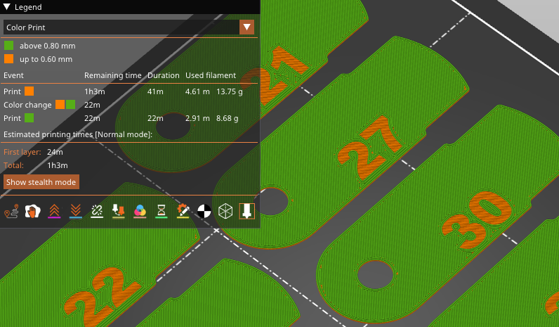
To get the most out of this model you need to setup a colour change. Use the ‘legend’ panel in the top left corner of the Preview to verify the colour change height.
The c-clips and pin halves are printed separately. Depending on the trust that you have in your printer, print more than one instance of each, these a tiny parts and even a small defect may render them useless.
Post Processing
For optimal operability sand down the high spots from the top layers. For that I simply used a sheet of wet sand paper on a flat surface. Optical smoothness isn't critical here, knock down the high spots with two to three strokes over the abrasive.
Assembly
I bet you can figure it out yourself, but anyway. Assembly works best when you put one of the c-clips on first, then connect the split pin halves and insert them into the stack. Put the second c clip on and you are good to go.
Customization
Find the Fusion 360 files in the download section. If you want to create a new value range, exporting a bunch of STL files will take forever, setup the Python script ‘parametric-stl-export.txt’ to do it automatically. You can find more info on that in the official Fusion 360 documentation. If you still struggle to do that, send me a DM or write a comment and I'll see how I can help; or if it's worth doing a video on automatic exports with Fusion 360.
To change the exported range update the two constants ata the top of the script.
MIN = 2
MAX = 30
To update the pin length accordingly set the n parameter in the 1007056-radius-gauge-pin.f3d file.