
Mini Optical Alignment Mechanism & Workbench
We calculate the final price from your selected file. You review and accept it before payment.
Saved on this device.
Model information
- Source
- Printables
- Category
- Other 3D Objects for Learning
- License
- Creative Commons — Attribution — Noncommercial — Share Alike
This Mini Optical Alignment Mechanism is a practical adjustment instrument designed to enable the precise positioning of lasers & optical components in all three dimensional spaces; i.e. X, Y, and Z. It includes a generic mounting platform for compatibility with a wide range of optical devices (with the use of an appropriate adapter); a dedicated mount for a 6mm dia. laser diode and a 25mm dia. mirror mount. The worm gear mechanism allows for smooth and accurate adjustments, ensuring optimal alignment in any test scenario. The design makes it an essential tool for any project requiring reliable positioning of optical components, from scientific or classroom experiments, to hobbyist projects, it delivers a cost-effective solution in a compact easy-to-use system.
STAY TUNED FOR UPCOMING PROJECTS INVOLVING THIS OPTICAL ALGINMENT MECHANISM!
Project Challenge #1: Lissajous Figure Laser Light-Show Pattern Generator & Projector by yba2cuo3 | Download free STL model | Printables.com
Features
- Adaptable Mini-Optical Workbench for Demonstration & Experimentation;
- 360° Fine-Tunable Alignment Mechanism in the X-Y direction using Worm Gears;
- ± 10° Z-Tilt Adjustment using 3-sided pivot springs & screws;
- 6mm dia. Laser Diode Mount;
- 25mm dia. Mirror Mount;
- Generic Component Mount to fit other optical components with custom adapters.
- Dimensions: 165x165x40mm
It is designed to be used with this mini-optical workbench: Mini Optical Workbench by yba2cuo3 | Download free STL model | Printables.com
Print Settings
- Printer brand: Prusa
- Model: i3 MK2S
- Supports: Yes
- Resolution: 0.15mm OPTIMAL
- Infill: 20%
- Brim: Yes - 10 to 20mm
- Filament brand: Doesn't matter
- Filament material: PLA
- Filament color: Doesn't matter
Construction
The construction is relatively simple, making use of M3 hardware. A list of assembly material is provided below, along with where it's used. Also check the description associated with each file for more assembly details.
Assembly Tips:
- Don't forget to insert the small printed sleeve inside the worm gear shaft hole to prevent wobbling;
- There are 3 elongated mounting holes in the Mini Optical Workbench. This is where the worm gear screw/shaft goes. The slot allows for the adjustment of the worm gear distance to the worm with the ability to achieve a smooth & consistent rotation between both parts. When tightening the shaft nut, make sure that it is tight enough to prevent lateral or up & down movement of the gear, but not too tight which would prevent the free rotation of the gear;
- The worm contact location on the worm gear can also be adjusted slightly; i.e. either ahead or behind the gear, by moving the position of the collars on the worm shaft;
- Make sure that there is minimum play between the collars & pillow blocks but not too tight also to allow the free rotation of the worm.
- If everything is properly adjusted, the worm & gear should turn freely without any skipping of teeth or seizing.
List of Required Assembly Hardware
All HW is Stainless Steel Button Head Hex Socket Head Cap Screws and Nuts, unless specified otherwise.
| Common (per Worm Gear Assembly) | ||
| Qty | Description | Where Used |
| 2 | M3 washer | Worm gear shaft washer - under screw head & nut |
| 1 | M3 Nyloc nut | Worm gear shaft nut - install under workbench |
| 4 | M3x8 screw | Pillow blocks |
| 2 | M3x8 screw | Collars used on worm to restrict travel |
| 1 | M3x8 screw | Knob at end of worm |
| 1 | M3x16 screw | Worm gear shaft |
| 3 | M3x16 screw | For Z-adjust. Secures worm gear to laser, mirror or generic mounts. |
| 3 | 4mm Spring | Ball point pen Compression Spring for Z-adjust. Wire Diameter 0.4mm x Outer Diameter 4mm x Length 15mm. Note: You can cut your ball point spring to the appropriate length. Check: Amazon-spring |
| Laser Mount | ||
| Qty | Description | Where Used |
| 2 | M3x8 screw | For Laser mount (top) |
| 1 | 6mm, 5mW Laser Diode | For Alignment of optical components. The wire leads will need to be soldered to the USB-c PCB; i.e. red wire to Vcc (or V marking on PCB) & blue (or black) to GND (or G). Check: Amazon-Laser |
| 2 | M3x8 screw | For installing the USB-c PCB on the Laser Bottom Mount |
| 1 | USB-c PCB | Female Socket for powering the +5VDC Laser. Use a standard +5VDC USB AC adapter. Check: Amazon-USBc |
| Mirror Mount (per) | ||
| Qty | Description | Where Used |
| 2 | M3x8 screw | For Mirror mount top |
| 1 | 25mm Mirror | For Alignment. Check: Amazon-Mirror |
| 1 | Tape | Double sided tape for securing mirrors on mounts |
| Generic Component Mount (per) | ||
| Qty | Description | Where Used |
| 2 | M3x8 screw | For mounting generic components with custom adapter. You will need to design your own custom adapter to fit your special parts you want to test. |
Post Processing Tools
- Deburring tool for removing excess plastic from printed parts
- Hand Drill or Drill Press (optional)
- 2.5mm or 7/64" drill bit for enlarging holes for M3 tap (optional)
DISCLAIMER:
This project incorporates a Class 3R (IIIa) laser with a power output of 5mW. This laser is designed for safe use under controlled conditions.
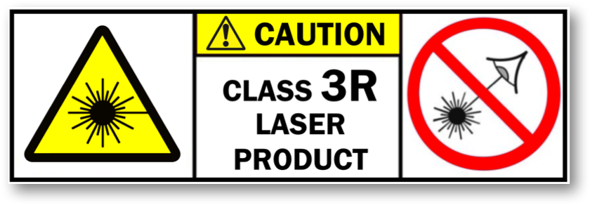
Safety Precautions:
- Do not stare into the laser beam directly.
- Avoid pointing the laser at reflective surfaces or at eyes.
- Keep out of reach of children.
- Use of protective eyewear is recommended for prolonged exposure.
By using this product, you acknowledge and accept all associated risks and responsibilities.