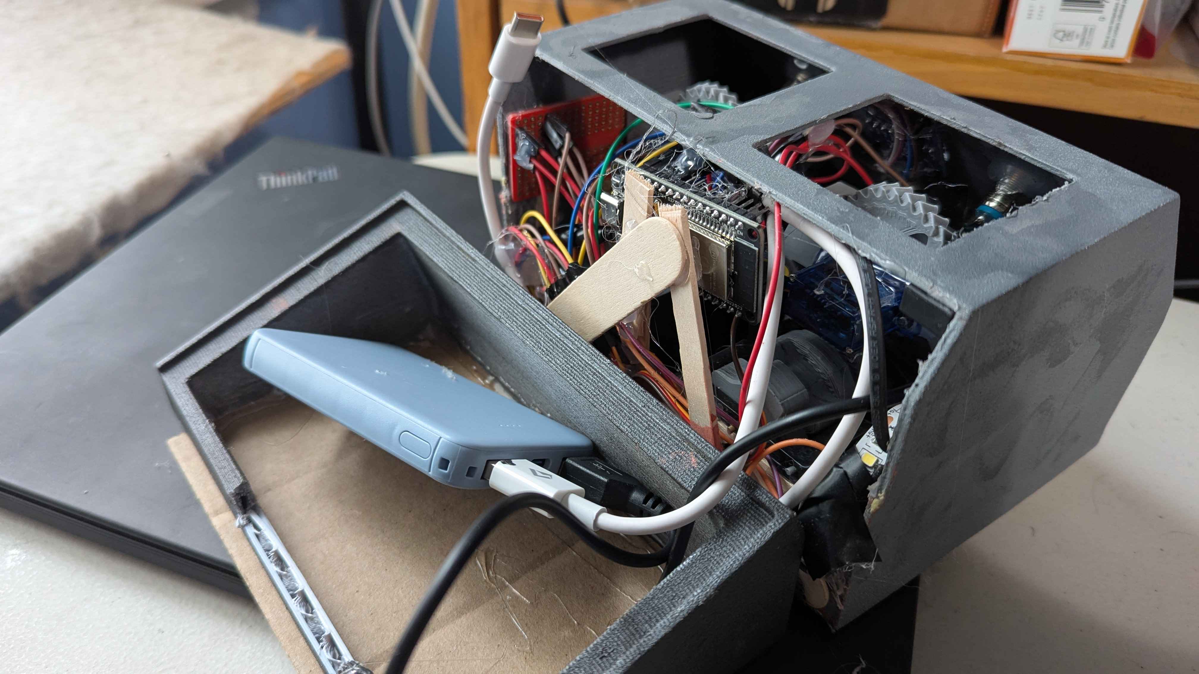
Analog Electronic Dice Roller [Prototype v0.5]
We calculate the final price from your selected file. You review and accept it before payment.
Saved on this device.
"Aren't all dice analog?" Using an esp32 driving two cam shafts to roll various combination of dice (d100,d20,d12,ect).
- Rating
- 0 / 5
- Likes
- 2
- Downloads
- 8
- Makes
- 0
- Views
- 128
- Reviews
- 0
Updated at source:
Model information
- Source
- Printables
- Category
- Miniature Gaming Accessories
- License
- Creative Commons — Attribution — Noncommercial — Share Alike
See it in action!
wow
Left Button changes dice from d100-d20-d12-d8-d6-d4.
Right button “rolls” the dice.

Heads Up!
This design crossed the finish line with luck and hot glue.
It's a workable, printable prototype, but it's far from perfect.
Consider this your fair warning:
- I'm releasing it into the wild as-is, with no plans for a polish-up.
- I built this all in TinkerCAD. If I ever learn a real CAD program I might revisit it.
- I will not assist with any build questions.
Print at your own risk, enjoy the ride and good luck!
Item List:
These are Amazon Affiliate links. If you use these links and purchase these items I will make money. If this isn't allowed (I sent Printables an email asking) I will remove without question.
USB LED Strip: https://amzn.to/3WS9sbV
Mini Solder-able Breadboard (Might be able to do without this, I just found it easier): https://amzn.to/4gtv5qc
Breadboard Jumper Wires: https://amzn.to/4hOcO87
ESP-32 Development Board: https://amzn.to/4jOiTmD
0.96 Inch 128x64 SSD1306 SPI I2C IIC Serial LCD Screen: https://amzn.to/4aNlrgI
Push Button Switch: https://amzn.to/4hMBaPr
9g Micro Servos: https://amzn.to/411Qdzh
Portable Charger, Power Bank: https://amzn.to/4hLNE9V
Some m2 bolts and nuts: https://amzn.to/3Q4U9ZI
Build Instructions:
I printed this with some generic PLA with a .6 nozzle at .32 layer height cause I'm impatient.
Step One: Follow build on Mechanical 7-segment Display, simple and smooth.
Print two of each, and 4 copies of the things that say 2 copy in the file name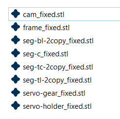
Print 2 of “newfaceplate.stl”
Print 1 of each:
- housing-stand.stl
- front-housing.stl
- back-housing.stl
May need some tree supports for the housing.
Use servo-dice2.ino and send it to the ESP.
Connect the wires from the servos, buttons, and screens for testing.
You'll need to figure out the proper values of the angles relation to numbers and update the arrays.
I did this via trial and error. If you open serial monitor in Ardunio it'll show you the current angle and what it thinks it rolled.
// Arrays for Left servo
float angleArrayLeft[] = {2, 19, 35, 53, 70, 87, 111, 120, 147, 155};
int numberArrayLeft[] = {6, 5, 4, 3, 2, 1, 10, 9, 8, 7};
float currentAngleLeft = angleArrayLeft[0];// Arrays for Right servo
float angleArrayRight[] = {165, 149, 131, 112.0, 93.0, 78, 57.9, 41, 23, 7.2};
int numberArrayRight[] = {10, 1, 2, 3, 4, 5, 6, 7, 8, 9};
float currentAngleRight = angleArrayRight[0];
I2C Communication Pins:
SDA_PIN 21- Used for I2C serial data communication.SCL_PIN 22- Used for I2C serial clock line.
Servo Motor Pins:
Servo servoLeftis attached toGPIO 23.Servo servoRightis attached toGPIO 13.
Button Pins:
rollButtonPin 12- GPIO pin for the roll button.modeButtonPin 14- GPIO pin for the mode selection button.
Ensure proper testing before next step.
Step Two: Add LED strips to the faceplates. Paint faces of numbers. I used a fluorescent paint to make it really pop.
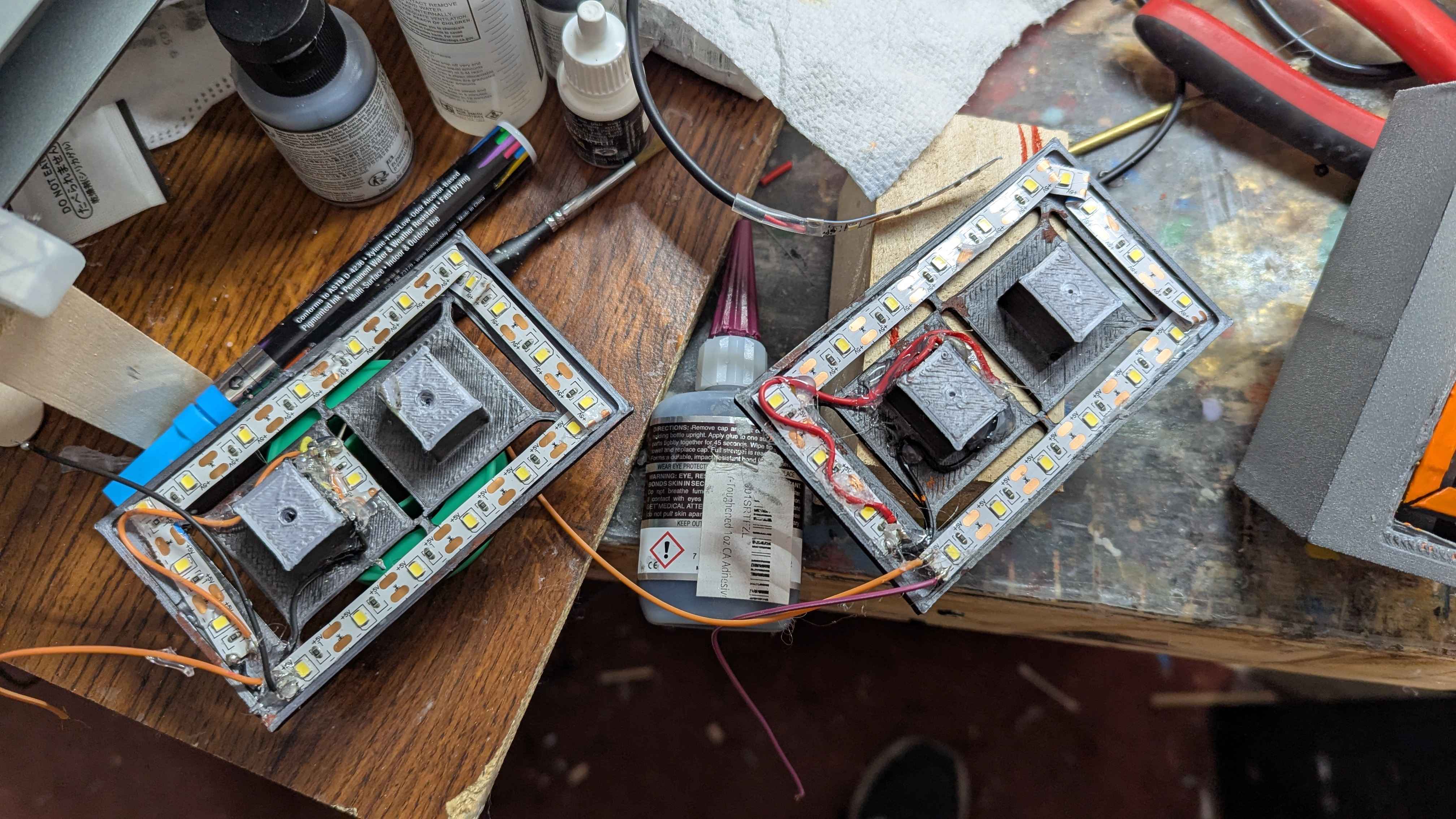
Step Three: Print housing, secure the faceplates to the housing, and then secure displays to the faceplates. This is to ensure everything is lined up. You'll want to add some supports to the displays. I did this with some scrap wood/popsicle sticks and hot glue. Continue with the rest of the build, adding the screen and buttons to the proper locations and securing the housing.
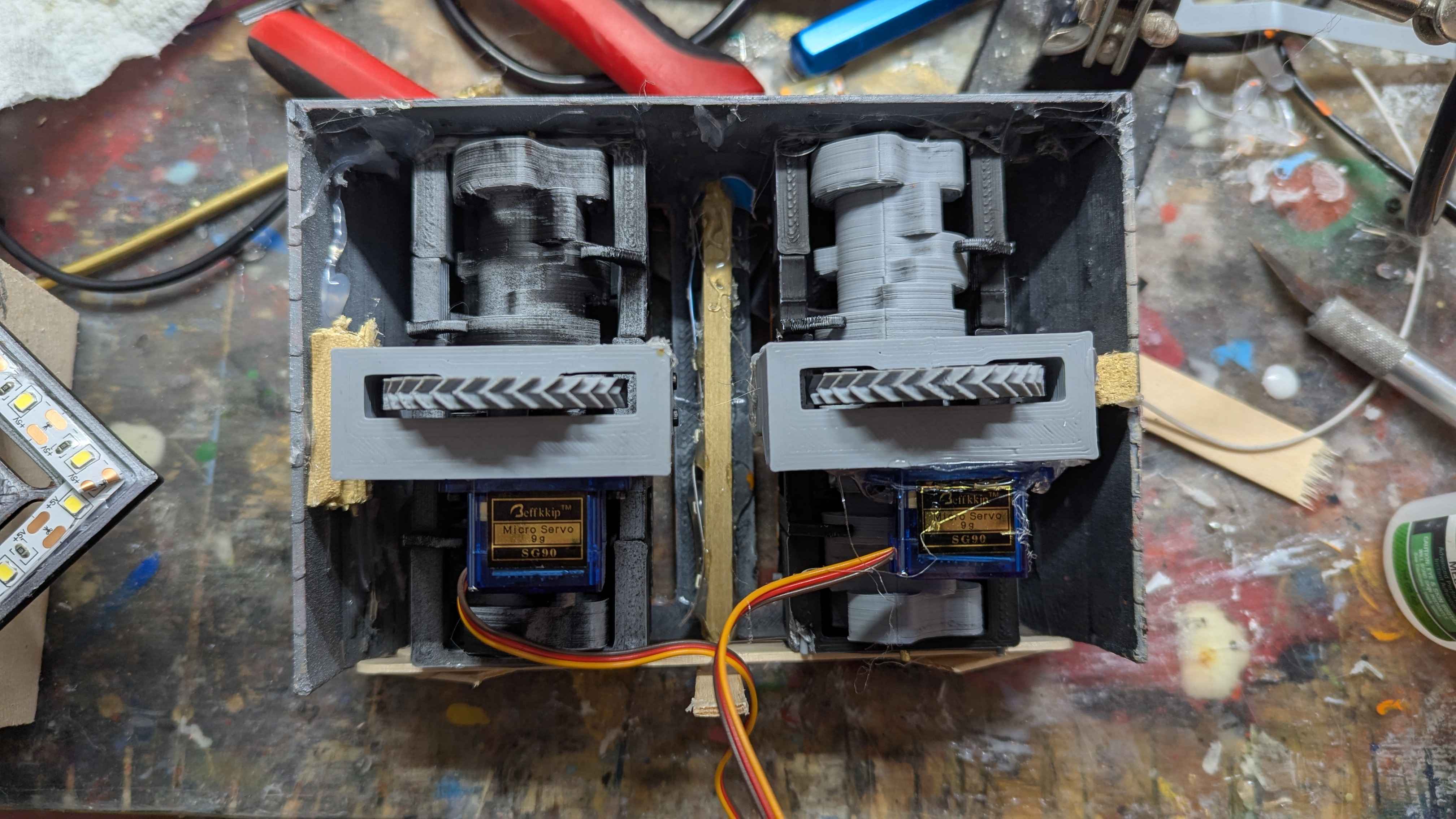
The main housing just rests on the stand. I added some cardboard to support the power bank.
The LEDS and ESP each run on its own USB. I added switches to mine and just hot glues them where they fit.
I did some post processing to mine, sanded and spray painted.
I did have to cut the back a bit to fit the ESP32. If my cable management was better it would have all fit without this. Version of the stand uploaded has this already removed, so you wont need to cut anything if you run into the same space issues as myself.