
Skeleten 10in Rack
We calculate the final price from your selected file. You review and accept it before payment.
Saved on this device.

A very strong, modular, easy-to-assemble 10-inch rack.
- Rating
- 5 / 5
- Likes
- 145
- Downloads
- 548
- Makes
- 6
- Views
- 6,566
- Reviews
- 5
Updated at source:
Model information
- Source
- Printables
- Category
- Computers
- License
- Creative Commons — Attribution — Noncommercial
This is the SKELETEN, a strong, modular, easy-to-assemble 10-inch rack. It is called the Skeleten because it features bone-shaped side supports and it is, well, a ten-inch rack.
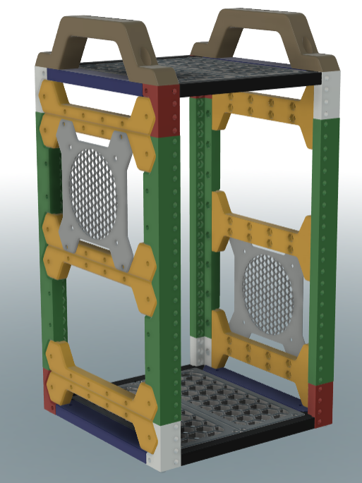
I wanted a strong, simple, modular 10-inch rack for my homelab. I looked online at everyone's designs and couldn't find anything I liked. So, I decided just to design and build my own.
This design focuses on ease-of-assembly, strength, durability, and functionality. It is not designed to be the least expensive 10U 10-in Rack on the internet. I'm 200lbs. I told my son I could probably stand on top of the assembled (but empty) rack, and it would probably support my weight. He dared me. I did it. It didn’t even make a sound. It held me up just fine with Elegoo Rapid PETG and 15% infill throughout.
As pictured, I used:
1.603kg of PETG
19g of PETG for supports
60ea. M6 x 20mm Screws (link below)
8ea. M6 x 15mm Screws (link below)
68ea. M6 Hex Nuts (link below)
I printed this in the aforementioned Elegoo Rapid PETG ( https://a.co/d/ir7cjUB ) since PLA can warp or deform with heat. You could use PLA for parts not exposed to heat, like the Handles and Fan Plates.
The picture shows it set up as a 10U rack, but it is designed to be capable of 2U (but why), 6U, 10U, 14U, 18U, etc. in increasing increments of 4U. For each additional 4U, just print 4 x 4U Rails and 2 additional Side Braces per 4U (uses 106g of PETG for each additional 4U section).
This uses M6 screws and nuts. I used these:
Screws:
- M6 x 20mm: https://a.co/d/cPuX2pR
- M6 x 15mm for the Bottom Plates. I used 8 ea.: https://a.co/d/aANE6bF
Nuts:
- M6: https://a.co/d/hCtZcup
The rails have recesses for the M6 nuts on every screw hole in the design. They range from a little loose in the socket to tight in the socket, depending on the printer's calibration and depending on part orientation during printing.
I used tree supports on the build plate for several of the models to support various recesses and overhangs. The supports you get on most slicers are very minimal.
For fans, the Fan Plate is designed to fit standard 120mm computer fans. I found a 2 pack of 120mm 5v USB fans on Amazon ( https://a.co/d/a1WPlPN ) that I just plugged into USB ports on the back of my firewall. These fans didn’t come with PC fan screws, but I had some on-hand.
Assembly (10U Rack, as pictured):
1. Print:
- 4 x Leg A (Pictured in Red)
- 4 x Leg B (Pictured in White)
- 4 x Side Bracket (Pictured in Blue)
- 4 x Front-Back Bracket (Pictured in Black)
- 6 x Side Brace (Bones, Pictured in Yellow)
- 8 x 4U Rail (Pictured in Green)
- 4 x Top-Bottom Plate (Pictured in Silver)
- 2 x Fan Panel (Pictured in Gray) (Optional)
- 2 x Handles (Pictured in Brown)
2. Build the top of the frame:

- Insert a nut in the hex recess on each end of 2 of the Front-Back Brackets (pictured in black) and 2 of the Side Brackets (pictured in blue) (the recesses are cut into the 45-degree angles).
- Using 2 x Leg A (pictured in red), and 2 x Leg B (pictured in white) pieces, screw the Side Brackets onto the Legs
- Screw the Front-Back Brackets into the legs with the notch/rabbit facing up as shown.
3. Build the bottom of the frame:

- Repeat all of the same steps as above but flip the notch/rabbit to face up on the Front-Back Brackets as shown.
4. Assemble the sides:

- Screw one of the Side Brace pieces (pictured in yellow) into the top frame on each side of the frame that you just built.
- Add 4U Rails (pictured in green) to the Side Braces.
- Add the other set of 4U Rails and Side Brackets to add another 4U to the rack.
5. Attach the bottom frame you built in step 3 in the same manner.
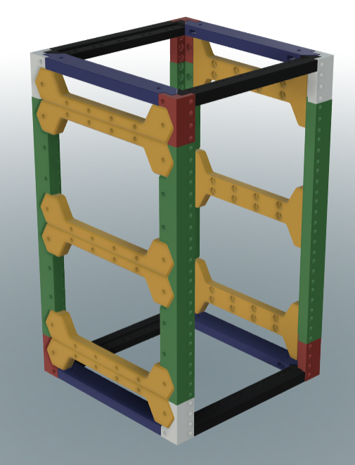
6. Add Fan Panels (pictured in gray) as desired.

7. Add the handles:

- On the top of the rack, slot a hex nut into the slot in the side of the Side Brackets (pictured in blue) and use something small to push them to the back of the slot if needed.
- Place a handle on top aligned with the holes and insert screws from the top.
8. Add the top and bottom plates:

- Insert the Top-Bottom Plates (pictured in silver) into the top and bottom of the rack. The bottom screws should be the 8ea. M6 x 15mm screws so that they don't protrude from the bottom.