
Nintendo 2DS D-Pad Conversion Mod
We calculate the final price from your selected file. You review and accept it before payment.
Saved on this device.
A 2DS D-Pad conversion to metal dome switches. Largely experimental.
- Rating
- 0 / 5
- Likes
- 0
- Downloads
- 3
- Makes
- 0
- Views
- 80
- Reviews
- 0
Updated at source:
Model information
- Source
- Printables
- Category
- Video Games
- License
- Creative Commons — Public Domain
Important notes:
A few permanent modifications will be done to the system shell. Modifications should not effect the OEM D-Pad setup.
The mod will raise the motherboard slightly. The four d-pad screws should not be overtightened.
This mod is experimental and has not been fully solved mainly from the awkward contact layout on the motherboard providing inconsistent and unsatisfactory button responses.
Print notes:
Slicer settings should prioritize precision. I would avoid fuzzy as it may prevent correct fit.
Printed with 0.4mm nozzle.
0.16mm layer height.
No adhesion brimming used for either prints.
You may need to trim away any unevenness from the PLA settling on the print bed.
Supports recommended for the d-pad spacer but keep them minimal.
Resources used for the mod:
Soldering iron with beveled (flat) tip.
High purity solder and flux.
Solder wick.
A dremel kit. I used this kit.
Box cutter blade for trimming excessive PLA and shaving tight spaces.
An original (old) 3DS d-pad membrane. Preferably OEM but 3rd party works.
An original (old) 3DS d-pad adhesive metal strip or 3rd party. Alternatives such as a switch joycon metal strip could work but requires cutting pieces out to fit over the d-pad contacts.
Assembly steps:
If printed parts are not fitting right, look for any print faults and spots to trim with the box cutter blade. You will likely need to trim any PLA which has settled on the print bed.
With the handheld disassembled down to the d-pad, apply tape around the screen edges in the d-pad area. This will help prevent plastic shavings from entering under the screen.
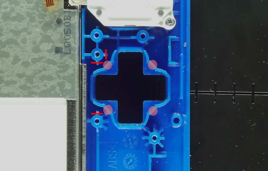
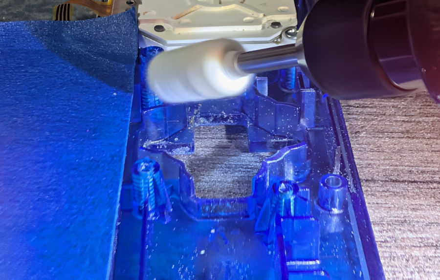
A few areas will need to be trimmed to fit the new rubber membrane. Take the dremel and box cutter blade to trim back the areas shown in the figure. Solid red lines are cut off areas using the box cutter blade. Cutting all the way down is not required -- only enough for the new d-pad membrane to fit. Red areas are shaved down a few millimeters using the dremel.
Print the d-pad membrane fitting and affix it on top of the d-pad housing. The thinner side of the fitting should be nearest to the screen.
Verify the new rubber d-pad membrane fits on top of the membrane fitting part. The edges should fit inside the rubber grooves.
Print the d-pad spacer and verify it fits flush against the bottom of the 2DS d-pad rocker.
With the d-pad spacer installed, place it inside the 2DS d-pad housing.
Affix the original 3DS d-pad membrane on top of the printed fitting that's installed to the d-pad housing.
Take an adhesive metal strip for the d-pad and adhere it to the d-pad contacts on the motherboard. Contacts should be raised up at least 0.25 mm by tinning them with solder.
Take an adhesive metal strip for the d-pad and adhere it to the d-pad contacts on the motherboard. It should remain relatively tactile after the soldering treatments. Use any solder wick if need be.
Place the motherboard back onto the shell and screw down a couple of the points over the d-pad. Careful not to nudge the rubber membrane out of place. I would recommend having the d-pad suspended to avoid it pressing up on the membrane.
Test the d-pad tactile feel. All directions should feel relatively the same.
Reconnect the ribbon cables to the motherboard for a response test. Full reassembly not needed. You can use the back shell to keep the battery in place for the test but mind its camera ribbon cable to not short components.
Try the new d-pad setup to test button response. I would use a button tester homebrew for checking.
Each direction should trigger appropriate while pressing down and stay activated for varying levels of pressure. Ideally, an activated direction in software should not release too early when relieving pressure.
This stage is a bit tricky and can take tedious soldering to achieve consistent and appropriate results.
Raised plastic supports on the back shell of the handheld may need trimming to prevent it from pushing down on the slightly raised motherboard.