
VPinball Backbox Support Files
We calculate the final price from your selected file. You review and accept it before payment.
Saved on this device.
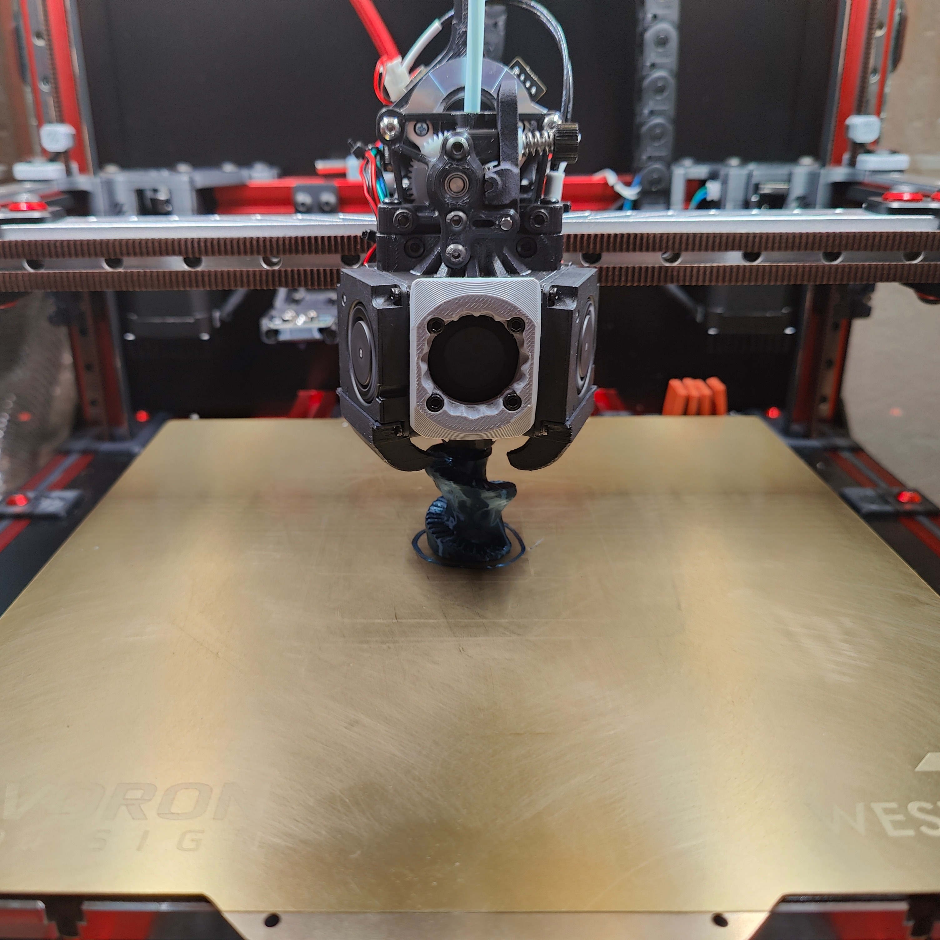
Various things to make building a Vpin backbox easier
- Rating
- 0 / 5
- Likes
- 3
- Downloads
- 33
- Makes
- 0
- Views
- 314
- Reviews
- 0
Updated at source:
Model information
- Source
- Printables
- Category
- Video Games
- License
- Creative Commons — Attribution — Noncommercial — Share Alike
This set of models are a collection of support files and other things needed to build the backbox for my vpinball cabinet. I've had a handful of questions about how I did this and requests to re-use these parts, so here it is, all in one spot.
---
The original CAD for my backbox is available here or the STEP file is included in the downloads.
WARNING: Please note that if you choose to use this, take this more as “inspiration” rather than an exact plan to follow. Even as I built it, I made minor adjustments as I went. Be safe when using power tools and always keep a present mind about what you're doing.
IMPORTANT: This DMD panel is a custom size with a width of 28.5 inches. This is slightly more narrow than the standard 32" backbox size. Custom spacers can be added to the DMD panel jig to add back the missing space if building to the standard size. It is very unlikely that this backbox will fit off-the-shelf backbox parts. This is more of a “money saving” design. It's best to measure the parts you're going to use and go with those dimensions.
---
Parts Used in Backbox Build
- Arzopa 15.6" 1080p monitor
- Mini HDMI to HDMI right angle adapter
- Display Port to HDMI cables (x2)
- USB C right angle adapter
- 20ft of T-molding
- RGB strip lights
- Polk DB571 speakers
- Virtuapin Speaker bracket (cut to length with a hacksaw since it's slightly longer)
---
DMD Panel
Tools required
- Router
- Router pattern bit
- Jigsaw
- Circular saw or table saw to cut sheets
The DMD panel is created by laminating two MDF sheets: A thicker, inner layer of ½" (pictured red) and an outer, thinner layer of ¼" (pictured orange). The thicker layer (red) is cut with two ovals for the speakers, and an area to fit the DMD 1080p screen. The thicker layer (orange) is cut with recesses for the speaker grill, and to show the visible area of the DMD screen.

Creating the Thicker DMD Panel
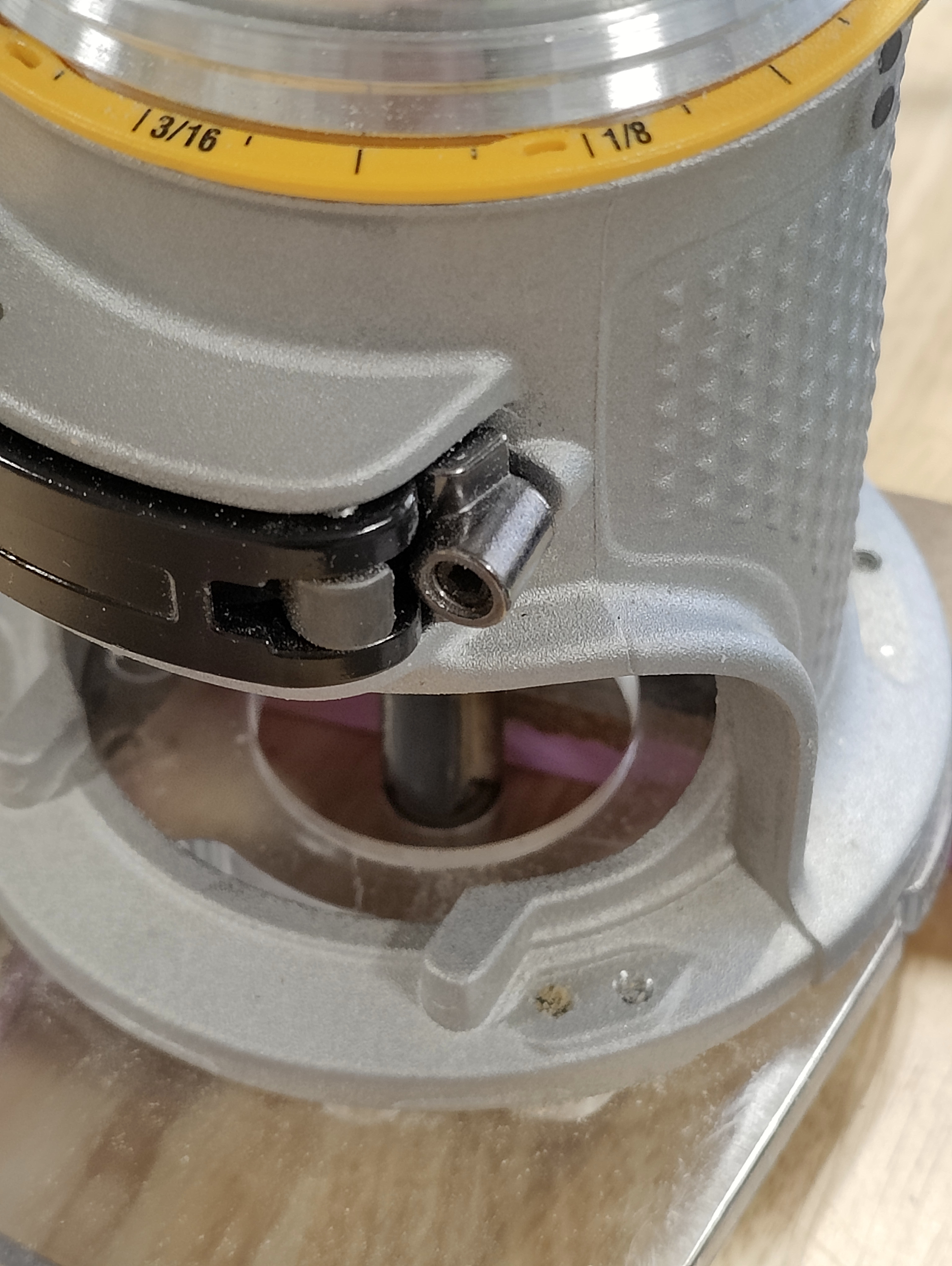
The file DMD Thicker Panel Drawing has dimensions for this inner panel. Cut out the area for the DMD screen with a jigsaw as best as possible. The file Speaker Pattern includes a router pattern jig for cutting out perfect ovals for the speakers. Rough cut these with a jigsaw first then clean up with a router pattern bit.

Creating the Thinner DMD Panel
The outer sheet can be cut to size with a table saw or equivalent. The files DMD Panel - Pattern XYZ can be bolted together to create a complete pattern for routing this front panel. This creates a clean, CNC-like look without the need for a CNC machine. As noted above, this panel is 28.5", which is slightly more narrow than the standard size. Spacers can be added to make it the standard size if needed.


Parts
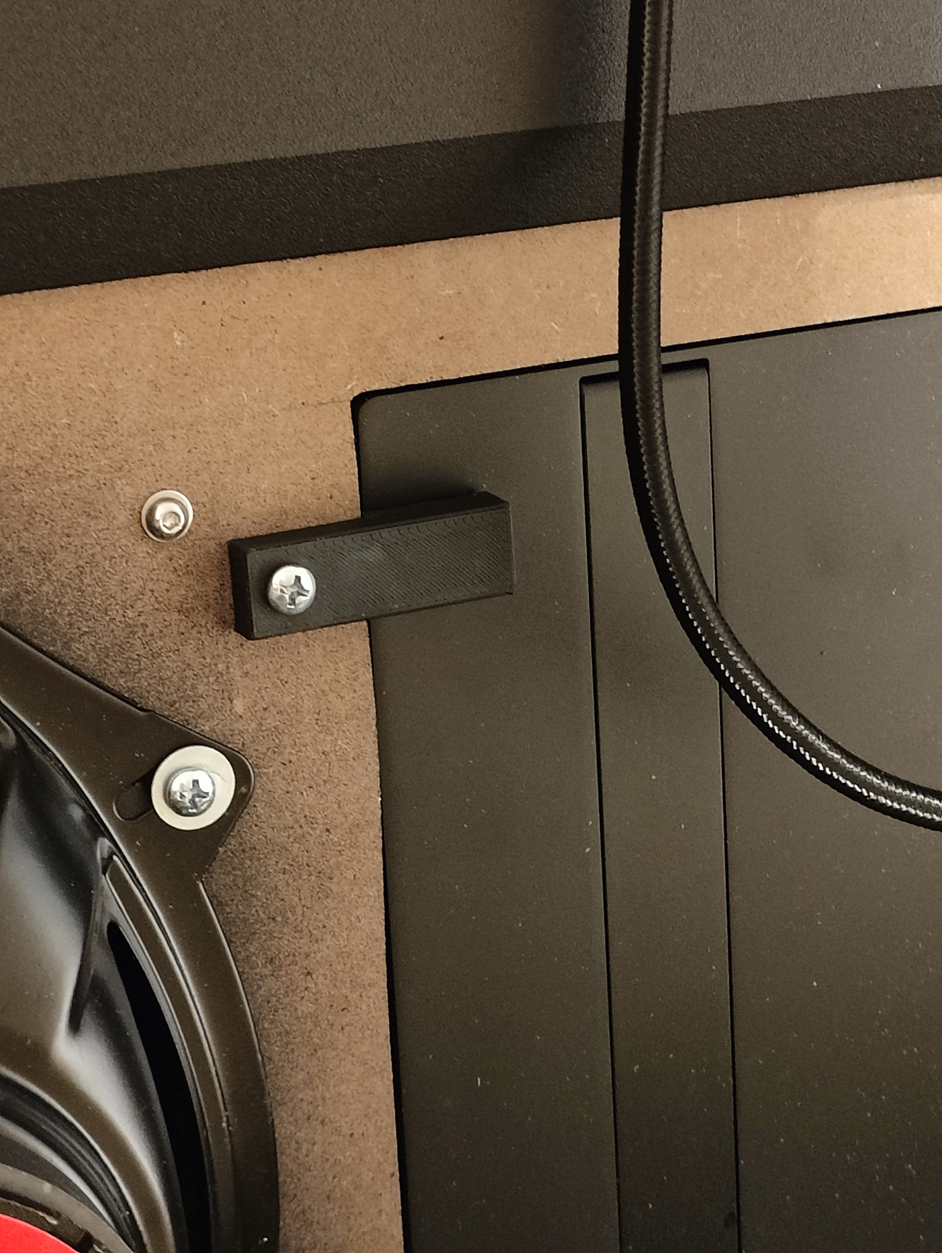
- DMD Panel Holder - Applies slight pressure to hold the DMD panel in place (pictured green above, see below)
- Screen Holder - Applies slight pressure to hold the DMD 1080p screen in place (see below)

---
Speakers
The speaker grills sit into a recess created by the front, thinner sheet of the DMD panel. The depth of the speaker grills is thick enough to accommodate LED strip lights. A few jigs are included to make installation easier. Grills required (8) 3mmx4.5mmx5mm heat inserts.
- Grill Drilling Jig - The speaker grills are screwed in from the back. This jig allows drilling the mounting holes for them perfectly aligned.
- Speaker Corner Marking Jig - When drilling holes to run the wires for the RGB LEDs through, this jig allows marking the exact center of the corner, if that's important to you.
