
Cage Buffer - An MMU Failed Buffer Design Experiment
Obliczymy ostateczną cenę na podstawie wybranego pliku. Sprawdzisz ją i zaakceptujesz przed płatnością.
Zapisane na tym urządzeniu.
Informacje o modelu
- Źródło
- Printables
- Kategoria
- Accessories
- Licencja
- GNU General Public License v2.0
I recommend this instead - https://www.printables.com/model/555238-mmu3-filament-path-design
This is new experimental concept for an MMU system where the retraction loop is contained around the spool using a “Cage Buffer”. Unfortunately there are better options but I did try this out so you don't have to. I was curious to see if this would work and needed to see! But I eventually reverted back to a slot buffer setup which you can see here:
https://www.youtube.com/shorts/p-DGKHfmRww
A single stiff non rotating fixed ring is placed against just one side of each spool, with six right angled arms that are positioned just over the spool edge. Each arm has two small panels on either end. The arms and their panels create a cage that contains the filament and prevents excess loops from going up and over the edge. The arms are adjustable in the up and down direction so you choose the height of the panels.
Here is a video showing this working - https://youtube.com/shorts/OvExgT7_2dc\
Advantages to this Buffer System
- No other buffer needed, the area around the spool serves as the MMU buffer
- Works with any spool, cardboard or plastic, adjustable for different spools
- Center Hub Design, uses exact sized center bearings hubs with metal rods going directly through the bearing center
- Reuses the MMU bearings you already have
- The buffer system doesn't add friction ot the system as it does not interfer with spool rotation in any way or even touch the spool.
- No gravity, tension, or extra PTFE tube lengths is added.
Disadvantages, but not show stoppers
- Requires printing a cage and hub for each spool, and requires a center bearing rod spool setup, so quite a bit to print, about 5-6 hours per spool (if you include the hubs too)
- For newer almost full spool the number of loose loops increases as the print goes on, and can add friction to the feed, although it still does work
- The cage arm panels can move on the arms so it is not foolproof and it is possible the filament can slide out, but not likely and I have not seen it happen in several 100 color changes so far
How this works
There are two parts to this, a non rotating and a rotating part. The filament spool and hub rotate of course, but cage buffer, and center spacer do not rotate and and are fixed in place so you can feed your PTFE tubes directly to them.
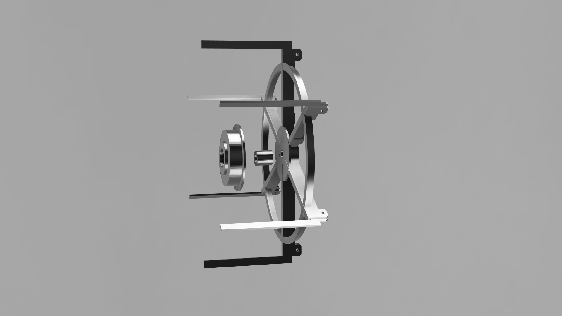
As the spool rotates, the cage ring does not move and is strongly secured against a non rotating spacer hub with a 5/16 inch nut on a 5/16 inch or 8mm threaded steel center rod. The spool then spins freely on a moving hub on dual bearings. The spacer only touches the inner bearings circle and not the hub or spool. Because both the spool and cage and centered precisely around a metal rod with a fixed with of 5/16 inch or 8mm, this enables this system of tight tolerances to work. The spacer hubs also come in any lengths which you can create, and ensures the ring is not in contact with the outer plastic or cardboard round sides of the spool. The hubs are exact fit and come in various sizes. I designed these exact fit hubs and spacers as well and have been using them with a slot buffer for a while. It is an almost frictionless sytem, which is a goal I had in preventing any friction along the path to the MMU, (except in a short curve which introduces static friction to prevent movement right before the MMU).
In the picture below you see the exact fit bearing hub on the left, the spacer and the cage buffer ring. Only the bearing hub rotates, and the non moving spacer positions the non moving ring 1-2mm away from the sides of the hub and filament spool, not touching either them and interfering with slowing them down.
What you Need
For each cage buffer you need:
- 1 printed cage ring (my design here)
- 6 printed cage arms (my design here)
- 12 small cage arm panels (my design here)
- 6 m3 hex nuts
- 6 m3 10mm or 12mm hex bolts
For the spool hub and rod you need:
- 2 exact fit printed hubs (https://www.printables.com/model/451919-performance-filament-spool-hub-various-exact-sizes )
- 2+ printed spacers (mix and match for fit as needed, same link as hubs)
- 2 bearings (the exact size as the ones that come with the MMU)
- 1 5/16 inch metal rod 4 or 4.5 inch long and matching nut (4.5 inch preferable for carboard spools)
- Custom spool/bracket system that
- Strongly position the metal rod with clearance on all sides
- Positions a PTFE tube termination point a few inches from the spool
The bearing hubs come in sizes from 50-62mm inner diameter, and the link is above to my design for that. The spacers are there at the same link. The spacers can be made in any size in the slicer by adjusting the Z height. The only other requirement is to position a 4 inch long 5/16 (8mm also works if you use metric) rod securely in space. I did this with a setup using wood and brackets from home depot. The filament coming into this also needs to have a PTFE tube end attachment close to the spool feeding directly to the MMU. See my other listings for all kinds of PTFE tube brackets, holders, and adjusters as well, some are shown in the pic and video.
About the New Arm Panel Part
I just added this new arm panel part shown below that attaches to the bars and fits inside against the inner walls and performs the containment. You use two on each bar, so 12x per spool. The bars now sit higher about 3mm above the spool edges when you use these. These are optional for half empty plastic spools but still help greatly, and are needed for full spools and cardboard spools, where the buffer loops linger around the outer edge more. This part successfully solved many of the problems I was having where filament would creep out on more full spools and cardboard spools.
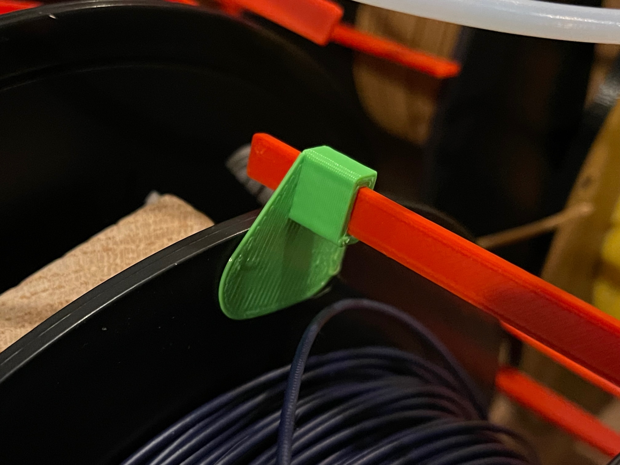
The arm panel has these characteristics:
- They are optional but help tremendously
- They slide on with a small amount of static friction.
- The panel is at a 2 degree angle to the arm, so the lower edge is closer to the spool wall.
- The panel is only 1mm thick so the filament does not catch on it.
- The more important panel is the outer one, since that end is not attached.
- The panel needs to overlap the edge of spool but not be so low as to touch the filement below. Keeping this in mind, then lower the arm as low as possible.
The arms have these characteristics:
- The two ends are identical is size and they are a right angle to each other
- The thickness is keyed to be able to be slide into the cage loosely, but the panels a little more tightly
- Feel free to experiment with different thicknesses by resizing the thickness in slicer if desired
The cage has these characteristics:
- Is only on one side of each spool
- Sits flush against a center spacer
- Is positioned about 2-4mm away from the side of the spool so as to be not in contact with the sides
- Has 6 slots with holes to insert arms and has screw to hold them in place and adjust them
- Is a rigid shape with a hole in the center for a 5/16 inch metal center rod
Everything here was printed in PLA with a .6 nozzle at a 3.0 layer height. I can confirm this design is now working fine with a test print of 100 color changes with the arm and panel new design changes, so it does work; however, I do not think this is best buffer solution.
Summary - Although it now works, I probably will not use this in the end
The problem is that the filament ends up in many many loose loops around the spool becuase the spool does not rewind as it is placed back on, especially on nearly full spools. The number of loose loops increase over time as the print goes on. Eventually there are so many loose loops that there is a increase in friction as the filament slides past and around all these loops as it is fed off the spool. I plan to abandon this experiment and go back to a slot buffer as my buffer, along with the spool and rod setup I am using here, as that part is very good and uses no friction.