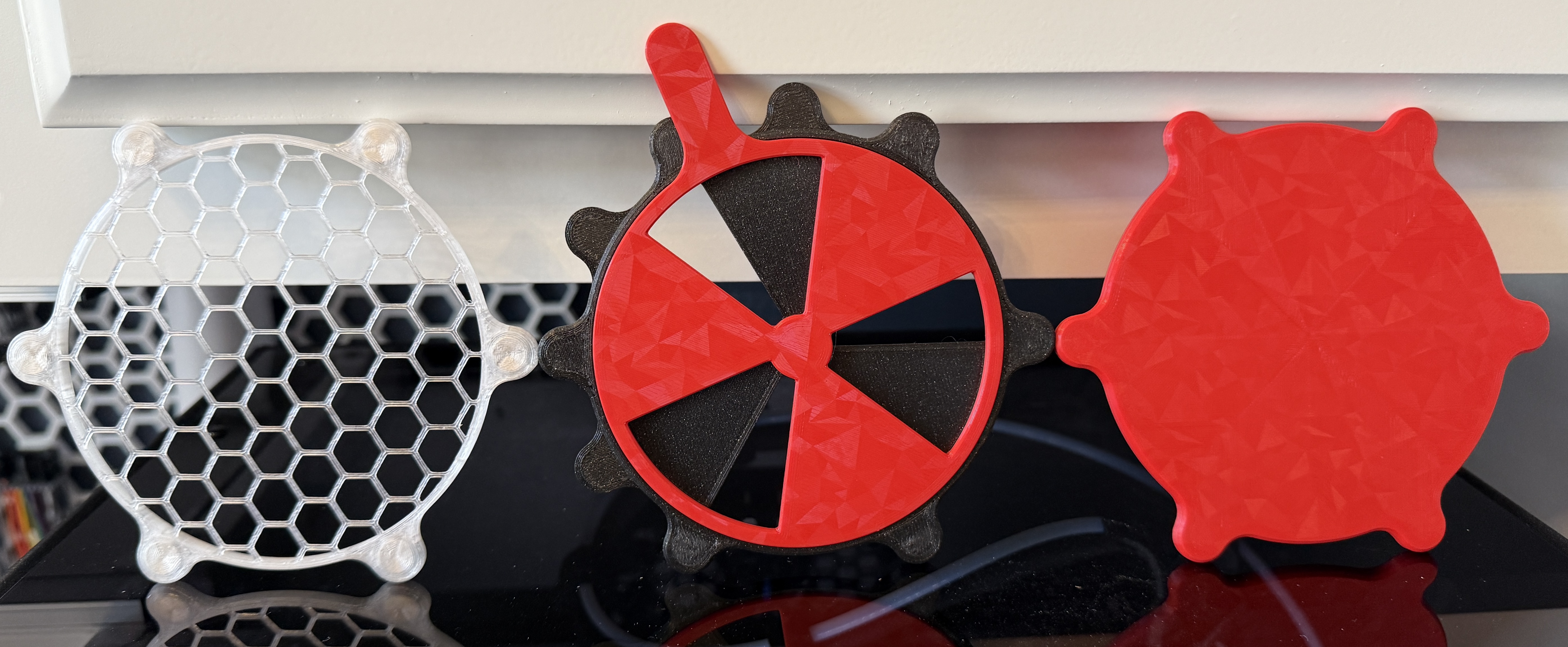
MagDuct Parametric CORE One Exhaust Adapter and Gasket (non-MagDuct adapter also included)
Obliczymy ostateczną cenę na podstawie wybranego pliku. Sprawdzisz ją i zaakceptujesz przed płatnością.
Zapisane na tym urządzeniu.

Adapts the non-circular non-duct-friendly exhaust geometry of the CORE One fan grid layout to MagDuct or basic ducting.
- Ocena
- 0 / 5
- Polubienia
- 19
- Pobrania
- 31
- Wydruki
- 0
- Wyświetlenia
- 466
- Oceny
- 0
Aktualizacja u źródła:
Informacje o modelu
- Źródło
- Printables
- Kategoria
- Prusa Parts & Upgrades
- Licencja
- Creative Commons — Attribution — Noncommercial — NoDerivatives
Motivation
I wanted to mount some ducting to my CORE One exhaust but did not like any of the currently available designs. I also wanted the ability to easily iterate on the design and its parameters.
Solution
Design and print a custom exhaust duct that achieves the following objectives:
Fully parametric providing customization of all dimensions
Styling consistent with the CORE One – I think the design looks pretty cool!
(optional) Gasket to print in TPU and insert between the duct and the CORE One
I am currently not using this, but it is available if you would like to use it. Let me know how it works!
Minimal material usage
Updates
v2.0
New! Added MagDuct compatible adapter!
Both the non-MagDuct (Ducting) and MagDuct bodies are available in the .f3d but the outer diameter for both is now 99.0 mm by default (instead of 72.5 mm that was used in v1.0). You can change that parameter and correct the broken features if you want v2.0 to be 72.5 mm.
MagDuct compatibility adds new features explained at the link above. For this reason, the MagDuct print file is now the primary file for this posting. But, again, the non-MagDuct files are also still available (just make sure you choose the one you intend to use 👍)
Added the four fan screw holes as additional attachment points. The top two screw holes eliminate the slight separation with v1.0. Reference the Installation section below for more details.
Adjusted the grid center point based on the CAD files provided by Prusa (v1.0 was off by 0.5 mm in X and Y)
Fixed loft control points for better symmetry
Added more solid geometry along the top for better rigidity
Design
In v1.0, the included design and model files were for the exhaust ducting that came with my xTool P2 laser cutter. The external diameter of the P2 exhaust port is 72.5 mm, so that is the dimension I used. Those files are still available in the v1.0 Model folders. But v2.0 introduces MagDuct compatibility with a 99.0 MagDuct diameter as discussed above.
Fixed in v2.0! *IMPORTANT NOTE – The bottom-right fan screw hole (when looking from the back) is ~2 mm to the right of the sketched position (i.e., it is asymmetrically wider). Reference this image of a printed template I used to confirm the exhaust geometry and dimensions to see what I mean. In this duct design, I accounted for that discrepancy with a large enough clearance.
Fixed in v2.0! Room for improvement? - The CORE One’s back panel should have included two additional screw holes at the horizontal midpoint. At the current base thickness of 2 mm, the top does separate just a little (~0.5 mm) under weight from the ducting hose. I am currently alright with this since it’s on the negative pressure side of the external exhaust fan but may thicken and reinforce this in a future iteration. If you elect to do this yourself, please let me know how it goes.
Customization
The Fusion file is included. You can customize the parameters (DESIGN | SOLID | MODIFY | Change Parameters) as necessary. When you open the Parameters dialog, first sort by name. The parameters most optimized for customization are favorited. The non-favorited parameters should work as well but may require more tinkering to repair broken downstream features.
Critical Parameters
THERE ARE THREE PARAMETERS WHICH ARE CRITICAL FOR MAGDUCT COMPATIBILITY. THEY MUST REMAIN CONSISTENT WITH ALL OTHER MAGDUCT DESIGNS. In the Fusion files, these parameters start with '_' and include:
_MagDuctDiameter - Outside diameter of the MagDuct template. If you have a duct that is already the right size for your ducting, you can most likely use that dimension for this parameter. But again, make sure that is the ducting you will use most throughout all designs you would like to be interchangeable.
_MagnetCount - Total number of magnets used in each template. Default is 6 as discussed in the design section above.
_MagnetSlotDiameter - Diameter of your magnets including tolerance
The MagnetSetback can be changed from the default of 0.6 mm — including down to 0.0 mm if you do not want to embed your magnets (not recommended for the mount ring since it's double-sided). In my testing, I found that 0.4 mm was a little thin to give the printer enough layers for smoothing over the bridging and provide enough strength to prevent the magnet from tearing out, but you may be able to dial this in better.
If you cannot get Fusion to work for you, please send me a message (see below) and I will post your requested model files at my earliest convenience.
Materials
(4) M3x8 screws
(recommended) (2) M3x35 screws
(optional) (4) M3 washers
(6 per side per interface) 8x3 neodymium magnets – I used these from Amazon.com
Of course, if you customize the size of the magnet slots, you will need those magnets instead
Printing
See the attached .3mf for my settings and model orientation. I printed with Prusament PETG Galaxy Black. Depending on the combination of your transition length and duct diameter paramaeters, you may require supports.
Supports
Supports should only be required with large MagDuct/ducting diameters and relatively short transition length parameters.
Magnets
If you plan to embed magnets during the print, ensure you have the following ready to go before starting the print:
Magnets
Pause(s) inserted at each layer immediately after an embedded magnet slot (the same layer that bridges to close the slot). These pauses should already be inserted in each of the Print and PrusaSlicer Project files but double-check before printing.
A plan for your desired polarity orientation.
With the default 6-magnet configuration, simply alternating North and South around the circumference will allow proper part alignment at each 120° of rotation.
If you care about the aesthetics of the parts, also consider the seam placement in relation to the magnet orientation. I set seam alignment to rear for all of the parts in the PrusaSlicer Project files.
Since these magnets are far from the magnetic bed, there is no force to hold them down, so I used magnets from underneath to hold them in place. Alternatively, a small dab of CA glue in each hole before inserting the magnet works well too. You could also play with the tolerances on the magnet slots to get them to print as tightly as possible while still allowing for trouble free insertion.


I prototyped on a Prusa CORE One.
Post-Processing
Remove supports and clean as required.
Installation
To use the top fan screws as additional attachment points, just replace the stock M3x30 fan screws with M3x35 screws. To ensure you properly thread into the adapter, start with both fan screws all the way in but not sticking out past the back face of the back panel threads. With the adapter's four corners already mounted and tightened, press on the adapter from the back in the top middle while further tightening the fan screws from the inside so that the screw's threads will properly bite into the adapter's screw holes. These pictures are from using M3x35 screws with a washer. Notice that the screw comes within ~1 mm of the back end of the threads. Additionally, if you try to wiggle the fans and fan plate inside, they should not move. You can try heat set inserts, but I elected not to since they would have to align perfectly with the back panel threads.


Questions
Please let me know if you have any questions (Messenger | Printables.com).
Shameless Plug
If this model helped you solve a problem, save some time, or in any way made your life a little easier then please consider clicking the Like button and posting your Makes! If it fell short after clicking on the title of the model, please let me know (Messenger | Printables.com). Either way, Thank you!
Related
Complete exhaust configuration
Adapters - Convert machine exhausts to ducting diameter and/or MagDuct
xTool P2 Exhaust Duct Adapter (configured as 4 in)
MagDuct xTool F2 Ultra UV Slip Adapter
MagDuct CORE One Exhaust Adapter and Gasket
Ducting
xTool pipe (included w/ xTool IF2 2.0 and xTool F2 Ultra UV)
xTool 72.5 mm ducting (included w/ xTool P2)
Couplers - Convert flexible ducting or pipe/rigid ducting to MagDuct
Connectors - Convert ducting for attachment to inline fan or external surface
Duct Expander (configured as 4 to 6 in expander)
Ducting to Window Insert Connector (attached to a piece of 1/4" acrylic inserted in the channels of my double hung windows which allows for quick installation/uninstallation (configured as 148.0 mm (6") and 72.5 mm exhaust port)
Inline Exhaust Fans
Mounts - Securely mount MagDuct components to a surface using a third-party mount
Accessories
MagDuct Fume Extraction Nozzle and Screen - Direct smoke and fumes (e.g., soldering) into exhaust ducting
MagDuct Generic Accessories - Control airflow volume and chamber temperature (e.g., enclosed 3D printers)