Luma Glow
We calculate the final price from your selected file. You review and accept it before payment.
Saved on this device.
Model information
- Source
- Printables
- Category
- Home Decor
- License
- Creative Commons — Attribution — Noncommercial — Share Alike
Intro
Designed to blend functionality with modern aesthetics, this lamp adds a stylish touch to any interior. It is optimized for use with WLED-controlled LED lights, giving you the freedom to customize brightness and colors to match your mood.
It is heavily inspired by this model, however its fully redone for better printing and assembly experience.
The FreeCAD file is included, allowing you to modify and improve this design. Feel free to share feedback or suggestions for future versions.
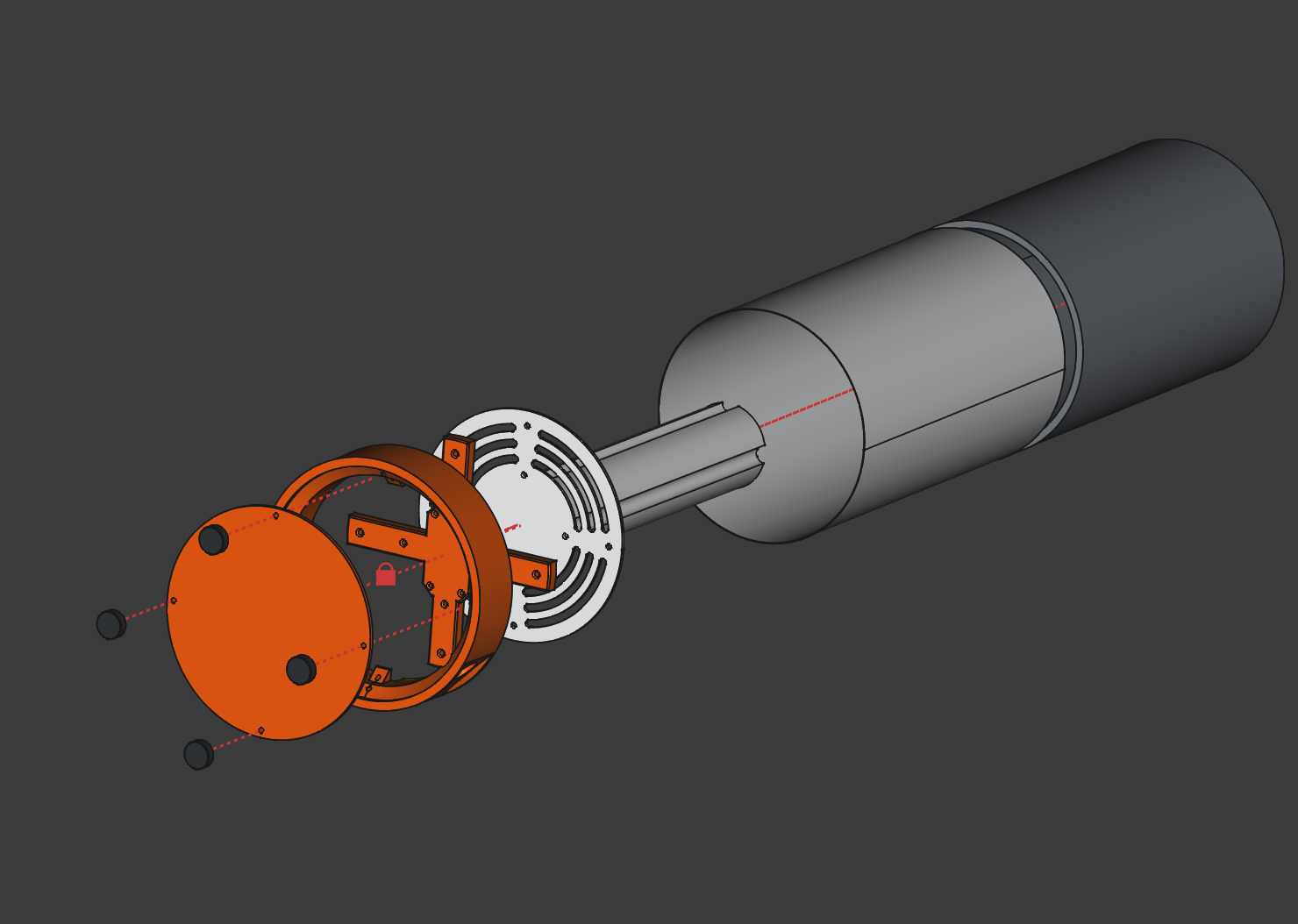
Parts
Here is the list of hardware I used for assembly:
| ESP32 (1 pcs) | https://a.aliexpress.com/_EHj5NnE |
| Type C female connector (1 pcs) | https://a.aliexpress.com/_EQebQwM |
| M3 bolts (14mm 8pcs, 10mm 8pcs) | https://a.aliexpress.com/_Ewct50M |
| Sensor button (1 pcs, optional) | https://a.aliexpress.com/_EGRJegs |
| WS2812b LED strip (60 diodes for regular, 30 for chubby) | https://a.aliexpress.com/_EzCyTAs |
| Pin headers (1 pcs, optional) | https://a.aliexpress.com/_Eyi9QFA |
| NFC stickers (optional) | https://a.aliexpress.com/_EuwZqJO |
You may use any other WLED-compatible board, but note that the mounting holes are specifically measured for this particular board. The space between the cross and the pole allows the use of zip ties if your board’s dimensions are slightly different.
Print instructions
Model features two versions of the lamp, regular and chubby.
For the chubby version, use the shortened variants of the pole, shade, and voronoi shade.
You can also skip the voronoi shade in your assembly, depending on your preference.
General:
- infill: 15% gyroid
- layer height: 0.2
- walls: 2
- material: PLA
Bottom:
- layer height: 0.28
- infill: 10%
Cross:
- layer height: 0.28
- infill: 10%
Feet:
- infill: 10%
- surface patterns: concentric
- material: TPU
Pole:
- infill: 3%
- layer height: 0.28
Shade:
- spiral vase mode
Voronoi shade:
- wall loops: 3
- line width: 0.6 or more to ensure better overhangs quality
Assembly
After printing all the components according to your chosen version, proceed to assemble the main structural parts.
Preparations
To install WLED to a board connect it to a PC and visit https://install.wled.me/
Here is a video covering all the process
ESP and cross
4 pcs of M3x10 screws
Be careful not to overtighten the screws to avoid damaging the board. You may want to tight the bolts in a cross pattern until board stops moving.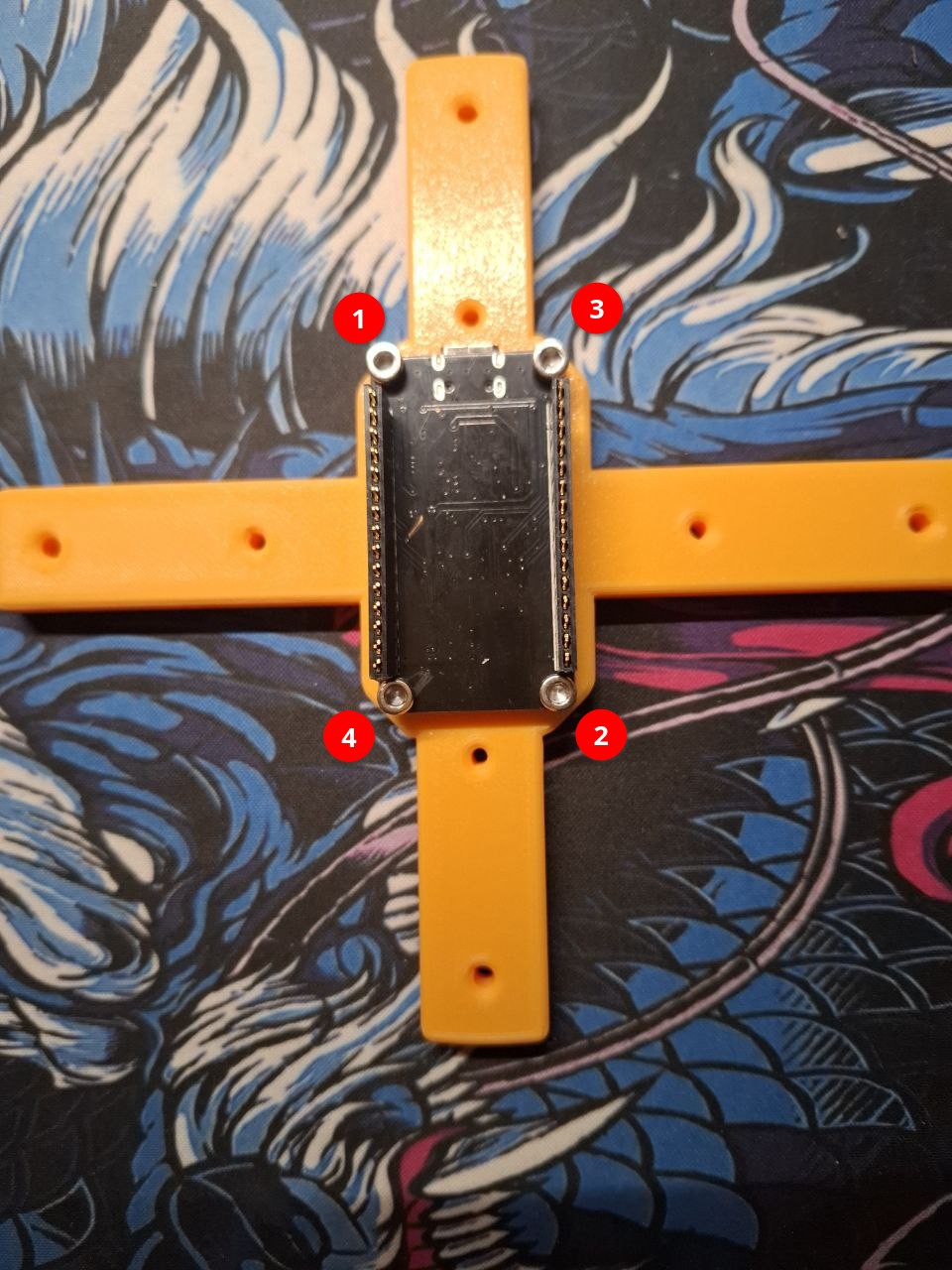
Cross and pole
4 pcs of M3x10 screws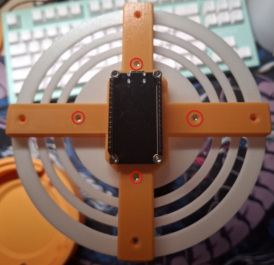
Body and bottom
4 pcs M3x14 screws.
Add a type C female connector and a button (optionally).
When inserting the connector, ensure it fits properly and is oriented correctly. Pull it out slightly and apply a dab of CA glue to secure it in place.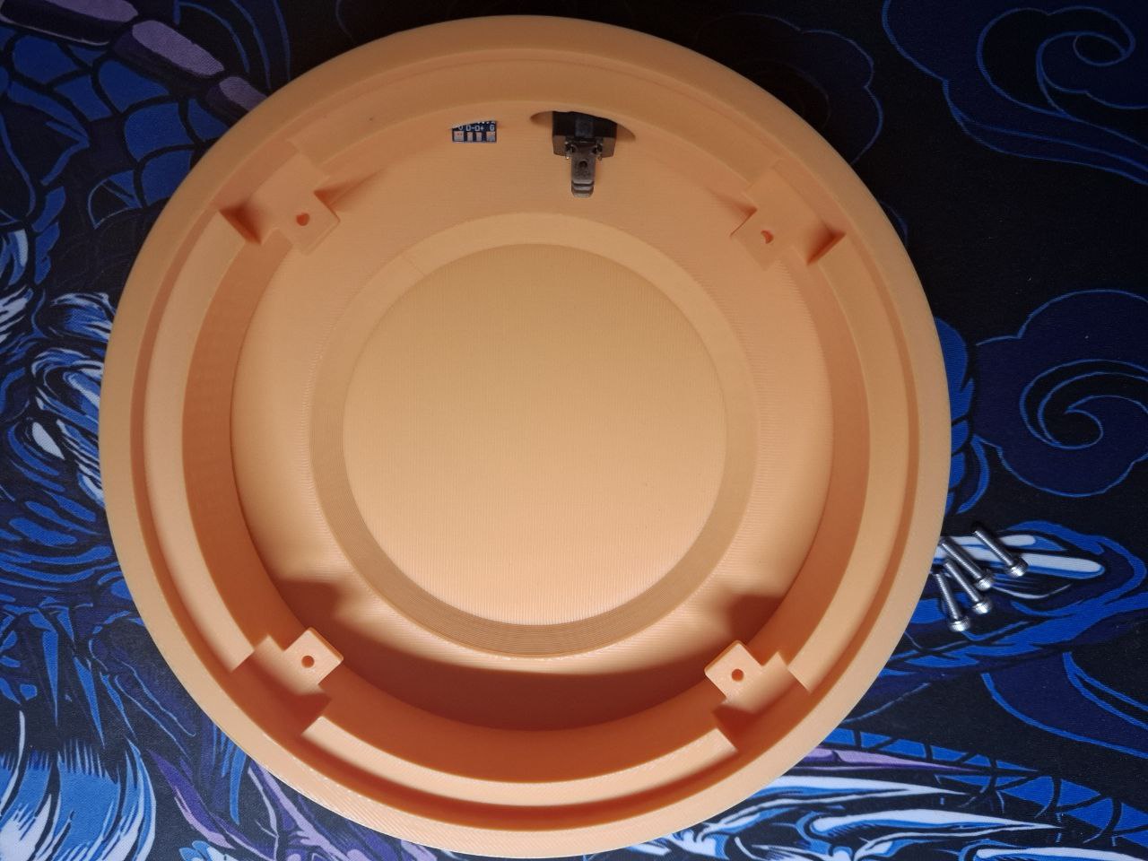
Wind a LED strip
For regular variant use 60 segments, 30 for chubby.
The LED strip should be wound around the pole with arrows pointing from the bottom to the top of the lamp.
After strip is fully winded I like to grab CA glue and additionally secure it once or twice every full turn as adhesive on the strip itself is not really strong.
After glue is done drying solder the wires to the points on a strip.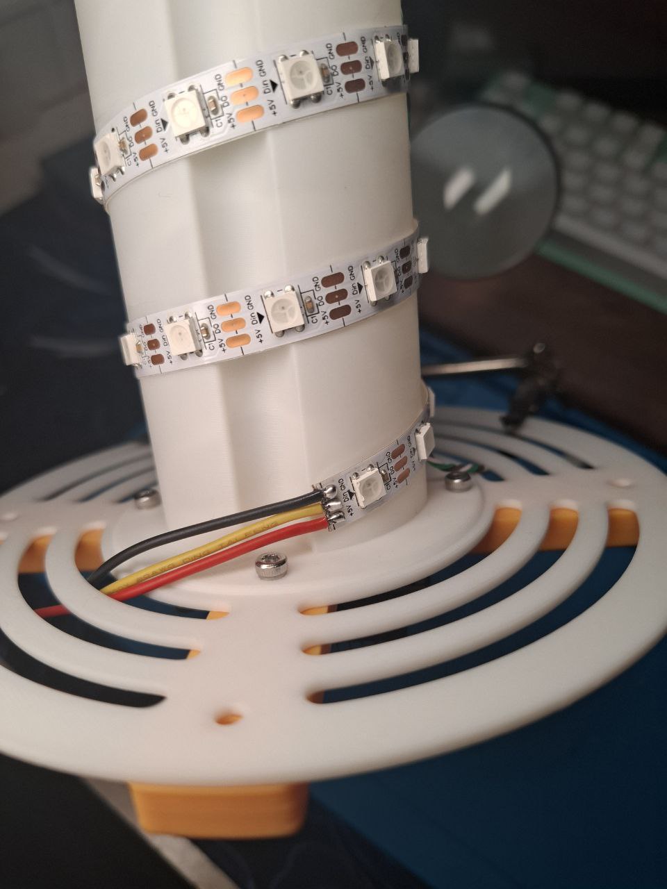
Button (Optional)
If you choose to use sensor button on a top of your lamp first you will need to prepare it by bridging the B pads and desoldering the test diode. It will make button hold its state like on\off switch and will not bother you with pretty bright red light.
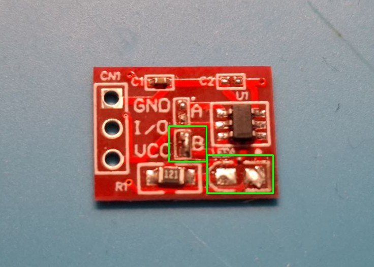
After it is done you now can solder the wire (simple twisted pair is enough).
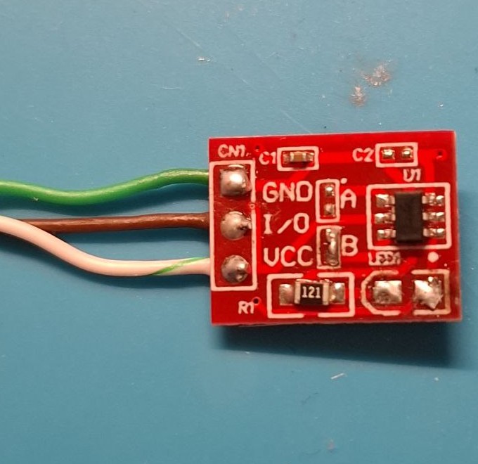
Then, route the wire through the cutout on the side of the pole to the bottom.
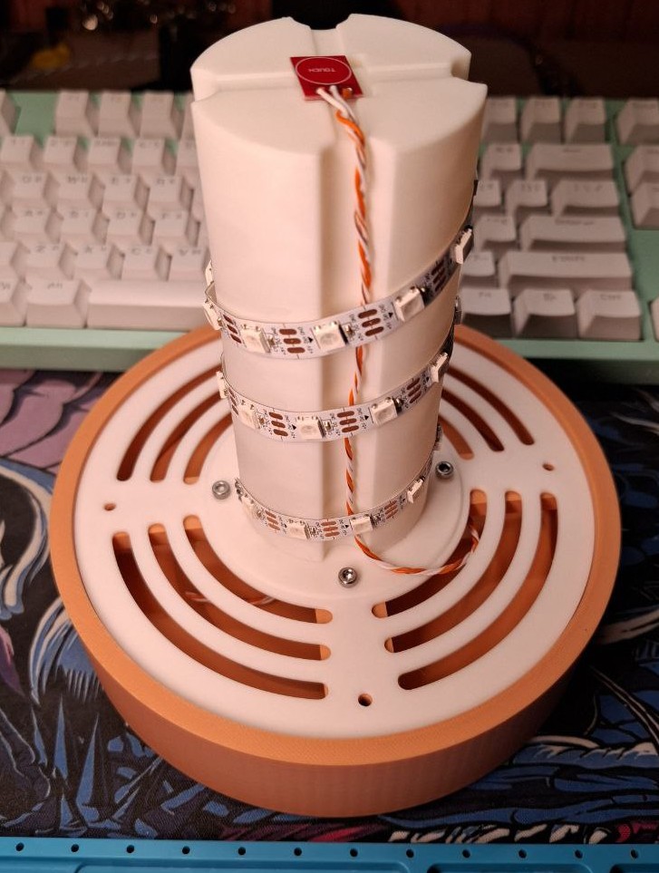
Before gluing it in place, check if it works. For now, simply leave it there.
Soldering
For cleanest results use wago connectors or other similar options.
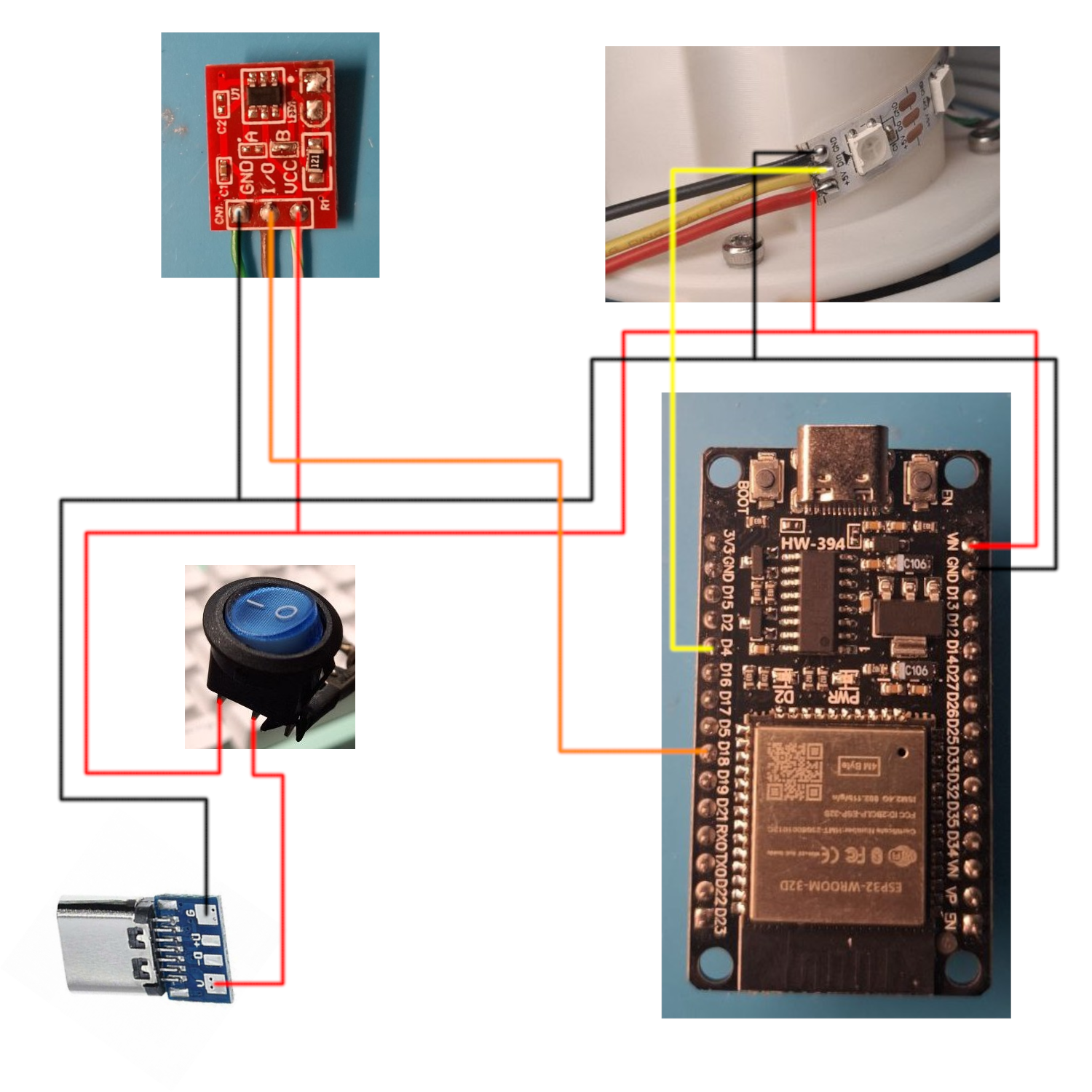
Here are the pins on ESP you need to mark before screwing it to the cross.
Or you may just use this image as a reference.
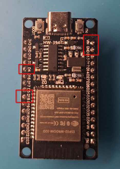
D4 is where the strip DIN wire should go
D18 is for button's I/O
VIN +5V and GND for ground.
All of the +5V wires should come together:
- Type C female connector - V+
- Button - VCC
- ESP - VIN
- LED strip - +5v
Same is all groud connections, which all marked as G or GND.
To not solder directly on a ESP pins I've used a headers.
Here how it looks with a ESP fully hooked up:
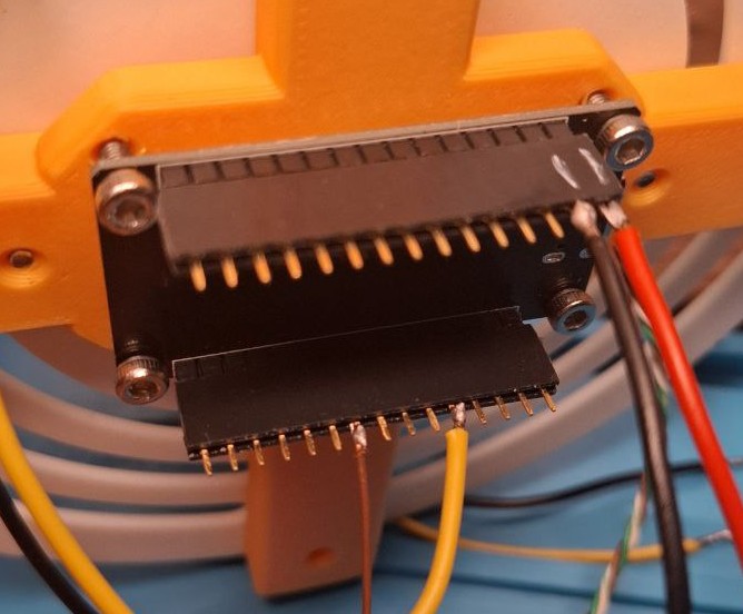
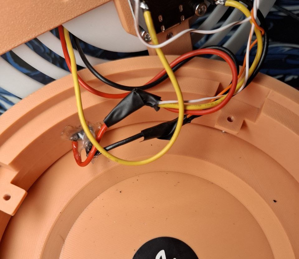
And this is how everything came together in my case.
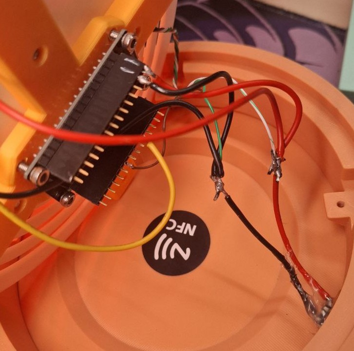
Trim pointy edges and wrap everything into an electrical tape.
Refer to the diagram below for wiring instructions.:
Setting up
After successful installation and assembly you will need to enter the setting and set
Optional parts
Button
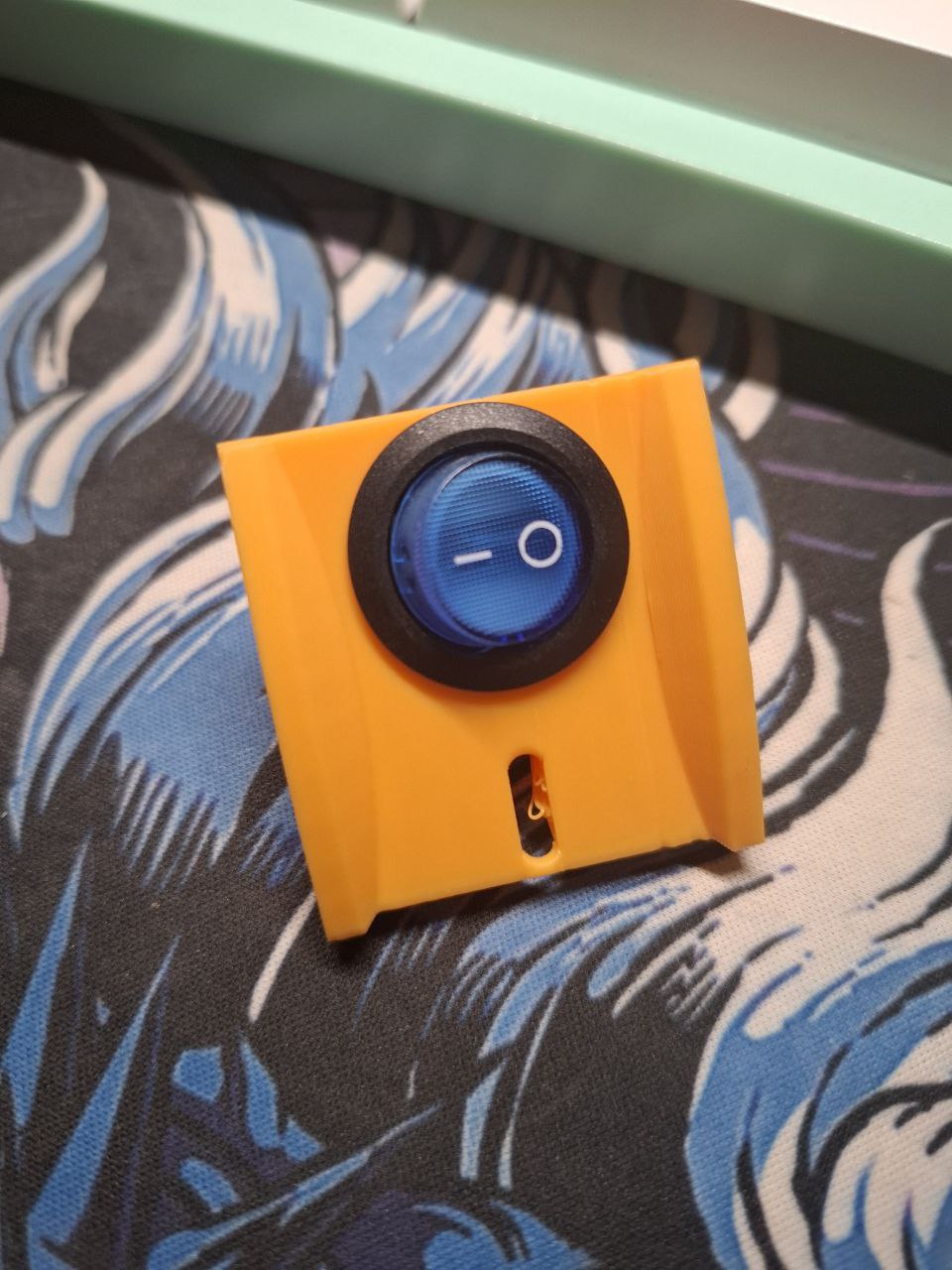
If you choose to use a button but your one is different - open your slicer and select the base model without a button.
Add a negative part to represent right size for your button, also cover almost all base with the negative parts to not print the whole thing.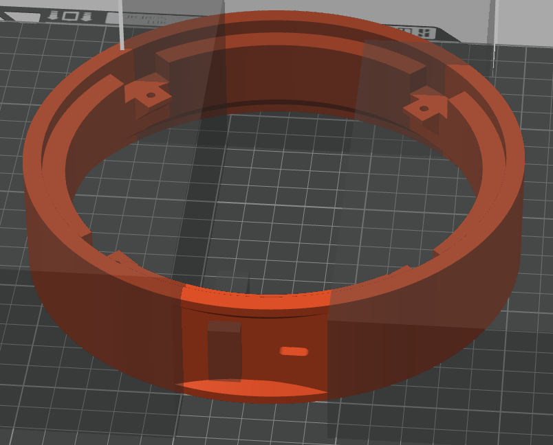
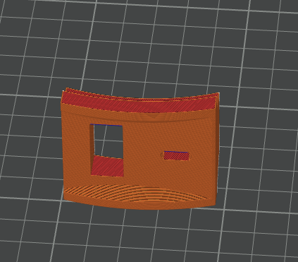
After printing check if its fit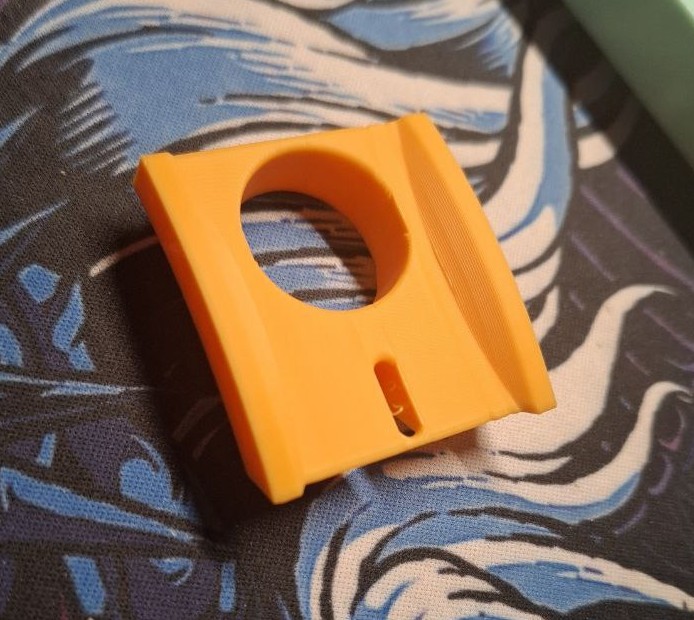
NFC tag
If you are planning to gift the lamp, consider adding an NFC tag with the default WLED access point to simplify the setup process.
Simply attach it to the inside of the bottom section and program it using your phone.
SSID: WLED-AP
Password: wled1234